Figure 45. Removing the drive backplane
3. To remove the cables from the PDB of the bottom layer, first Remove the storage tray, and then Remove the system board
tray. Disconnect the backplane cables connected on the PSB of the bottom layer.
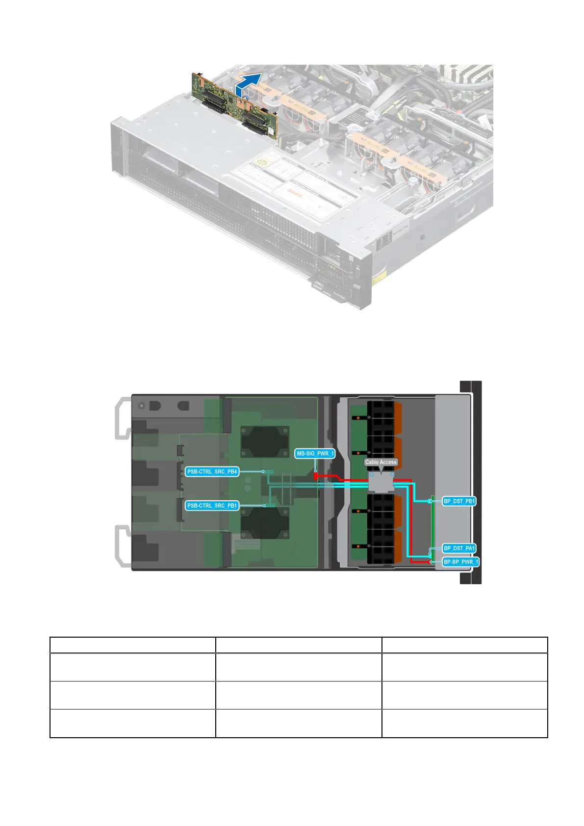
Figure 46. Cabling diagram
Table 65. 4 x 2.5-inch backplane cable connections
Order From To
1 MB-SIG_PWR_1 (system board power
connector)
BP-BP_PWR_1 (backplane signal
connector)
2 PSB-CTRL_SRC_PB4 (signal
connector on system board)
BP_DST_PB1 (backplane signal
connector )
3 PSB-CTRL_SRC_PB1 (signal connector
on system board)
BP_DST_PA1 (backplane signal
connector )
Installing and removing system components 85