AX-Series Motion Controller Instructions Manual Chapter 2
213
Troubleshooting
When an error occurs in the instruction execution, bError of the instruction changes to True. To confirm
current error state, see the error code in ErrorID.
Programming Example
In this example, the pulse output axis performs the homing motion via DMC_Home_P after the axis is
configured in the IO configuration interface.
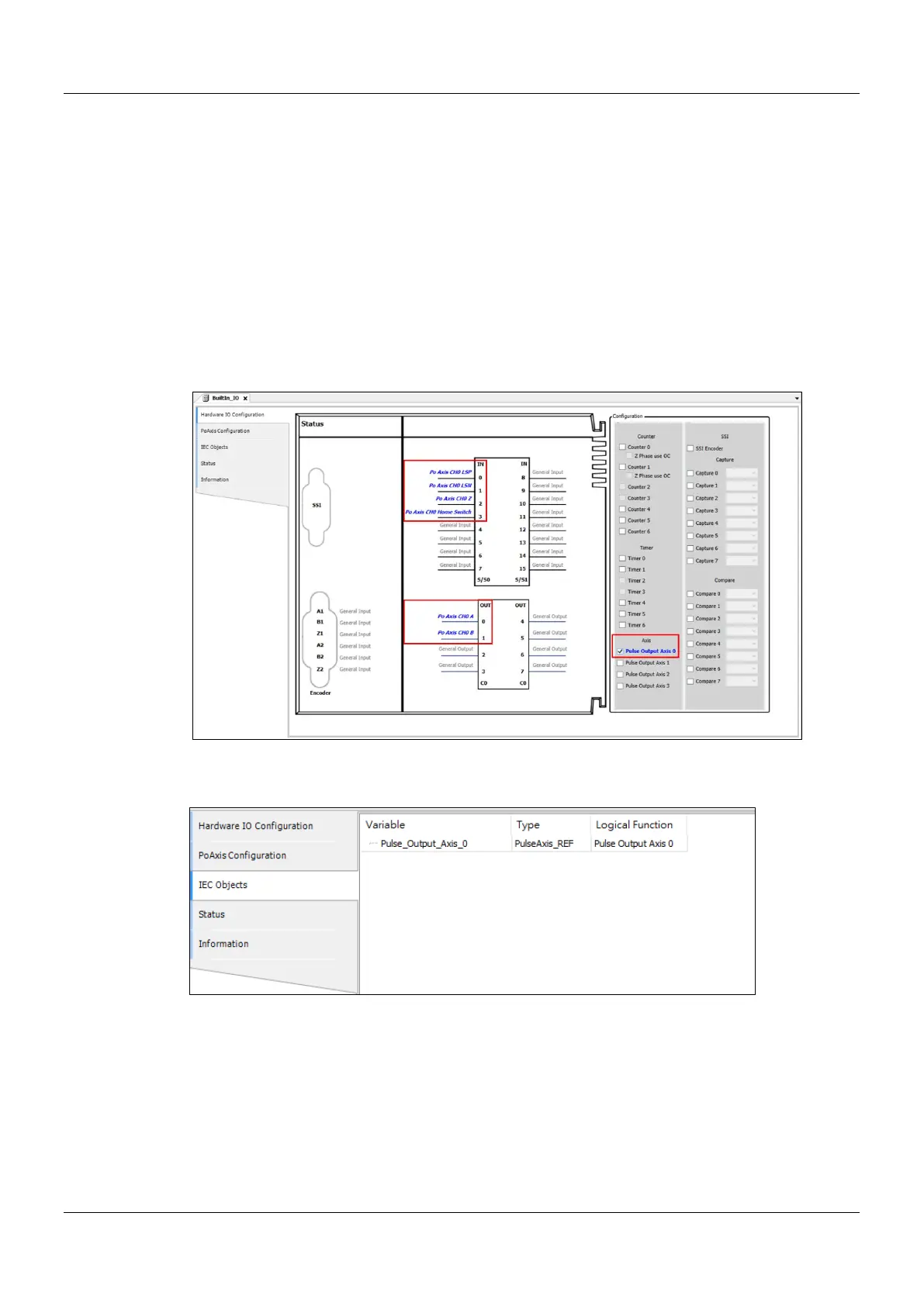
Select the first pulse output axis (Pulse Output Axis 0) in Hardware IO Configuration of BuiltIn_IO as below.
Then you can see corresponding output points (e.g. OUT0, OUT1) and signal trigger points for pulse output
(e.g. IN0, IN1, IN2 and IN3) from the software. The homing motion cannot be performed until the signal
trigger points for the homing mode have been configured to corresponding input signal sources.
After the configuration of the pulse output axis, the variable Pulse_Output_Axis_0 configured in IEC Objects
can be taken out as a Data Type to any function block, as shown below.
Pulse_Output_Axis_0 is connected to the input Axis of MC_ Power and DMC_ Home_P as shown in the figure
below. When the axis is in Standstill state, the instruction has started to perform the homing motion according
to the set homing mode. At the moment, the state machine will switch the state from Standstill to Homing.
 Loading...

