EasyManuals Logo
Home>Delta>Controller>AX Series

Delta AX Series User Manual

Delta AX Series
574 pages
To Next Page IconTo Next Page
To Previous Page IconTo Previous Page
Page #381 background imageLoading...
Page #381 background image
AX-Series Motion Controller Instructions Manual Chapter 2
376
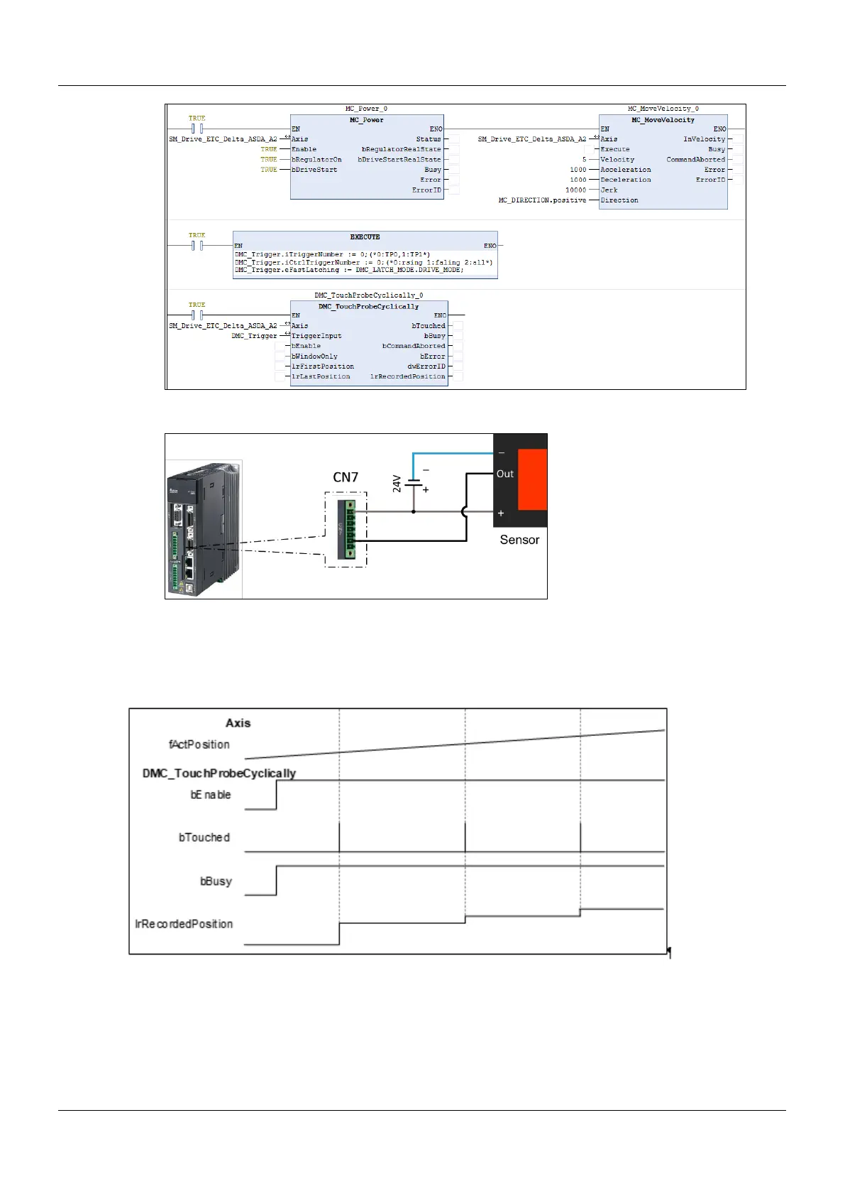
Wiring figure
1. The trigger signal comes from DI13 of extension DIs of the servo drives CN7. refer to the wiring figure
above for configuration.
2. In this example, the TouchProbe 1 trigger is taken as an example and so the photoelectric switch is connected
to DI13. If the TouchProbe 2 trigger is selected, the photoelectric switch should be connected to DI14.
Timing Diagram

Table of Contents

Questions and Answers:

Question and Answer IconNeed help?

Do you have a question about the Delta AX Series and is the answer not in the manual?

Delta AX Series Specifications

General IconGeneral
BrandDelta
ModelAX Series
CategoryController
LanguageEnglish

Related product manuals