8 | Components description
124 AXH1230‐UK ﴾ENG﴿ ‐ Apollo KM
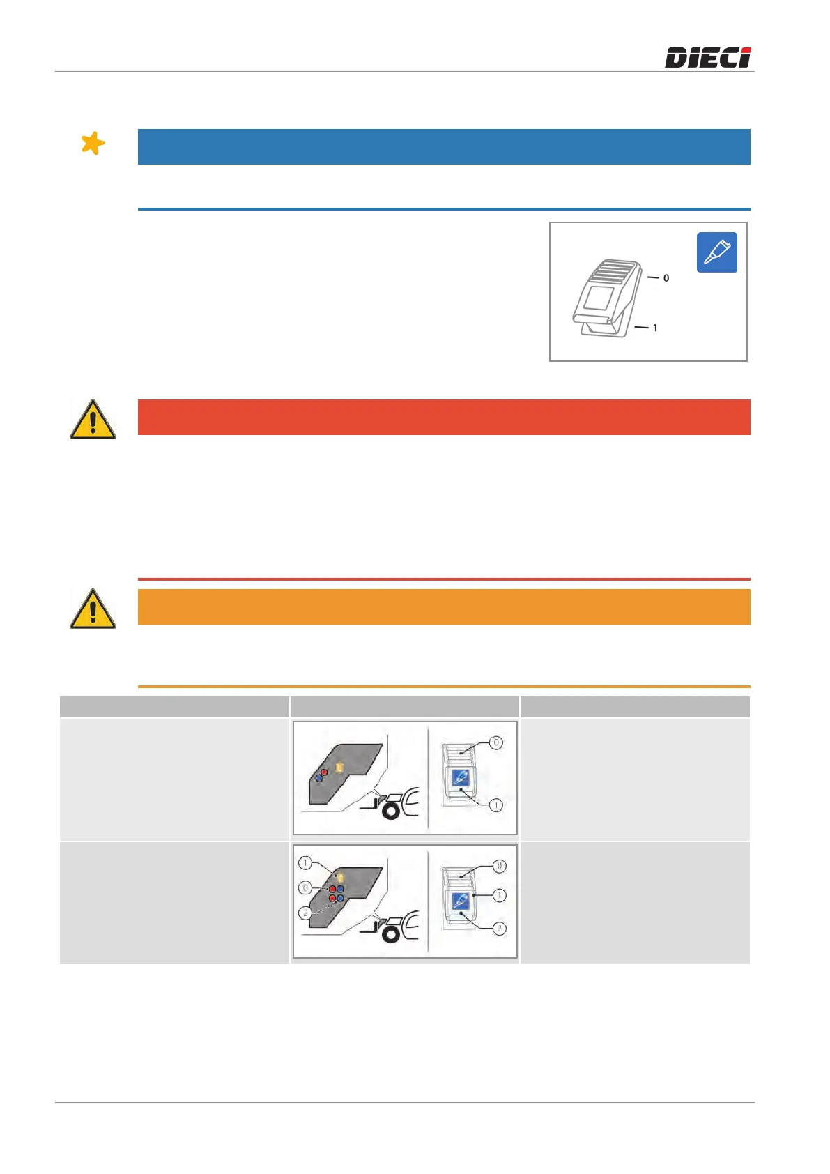
8.10 Hydraulic sockets and electrical contact on boom head *
NOTICE
* The presence and number of hydraulic sockets and electrical contacts present on the boom head may
vary depending on optional equipment.
Thesocketsswitchontheboomhead(fig.1502031)hasseveral
functions and positions depending on the optional equipment
installedonthevehicle.
Onceselectedthedesiredhydraulicsocket,itisnecessarytouse
the services lever on the joystick to operate the desired
movement.
150203-1
DANGER
Danger of moving the wrong hydraulic socket.
Do not operate the hydraulic sockets using the joystick during the selection of the hydraulic socket. Make
the selection of the hydraulic socket and use the joystick to control the hydraulic socket selected only at a
later time.
After connecting the equipment to the hydraulic sockets before starting the job, check in a safe location
that all the controls are working properly. During the test, be careful not to create danger or damage to
persons, animals or things.
WARNING
Pay attention to the connections of the hydraulic socket: moving the service lever placed on the joystick
forward, towards the open padlock (see Joystick chapter) oil will be sent to the sockets marked with the
color BLUE or by the symbol “+”.
Installation Diagram Switch description
Standard hydraulic socket
+ Electrical contact
0Electricalcontactoff
1Electricalcontacton
Standard hydraulic socket
+ Additional hydraulic socket
+ Electrical contact
0Standardhydraulicsocket
1Electricalcontacton
2Additionalhydraulicsocket