Manage End Devices End Device configuration
Digi XBee® 3 Zigbee® RF Module
153
device must drive it low to wake the device. All other pins are left unmodified during sleep so that they
can operate as previously configured by the user. The device does not respond to serial or RF data
when it is sleeping.
Applications that must communicate serially to sleeping end devices are encouraged to observe CTS
flow control.
When the device wakes from sleep, it asserts (high) the On/Sleep pin, and if it enables flow control, it
also asserts (low) the CTS pin. The associate LED and all other pins resume their former configured
operation. If the device has not joined a network, it scans all SC channels after waking to try and find a
valid network to join.
Pin sleep
Pin sleep allows the module to sleep and wake according to the state of the DTR/SLEEP_RQ pin (Micro
pin 9/SMT pin 10/TH pin 9). Pin sleep mode is enabled by setting the SM command to 1.
When the device asserts (high) DTR/SLEEP_RQ, it finishes any transmit or receive operations for the
current packet that is processing and enters a low power state. For example, if the device has not
joined a network and SLEEP_RQ is asserted (high), it sleeps once the current join attempt completes
(that is, when scanning for a valid network completes). The device wakes from pin sleep when the
SLEEP_RQ pin is de-asserted (low).
Devices with SPI functionality can use the SPI_SSEL pin instead of D8 for pin sleep control. If D8 = 0
and P7 = 1 , SPI_ SSEL takes the place of DTR/SLEEP_RQ and functions as described above. In order to
use SPI_ SSEL for sleep control while communicating on the UART, the other SPI pins must be disabled
(set P5 , P6 , and P8 to 0 ). See Low power operation for information on using SPI_SSEL for sleep
control while communicating over SPI.
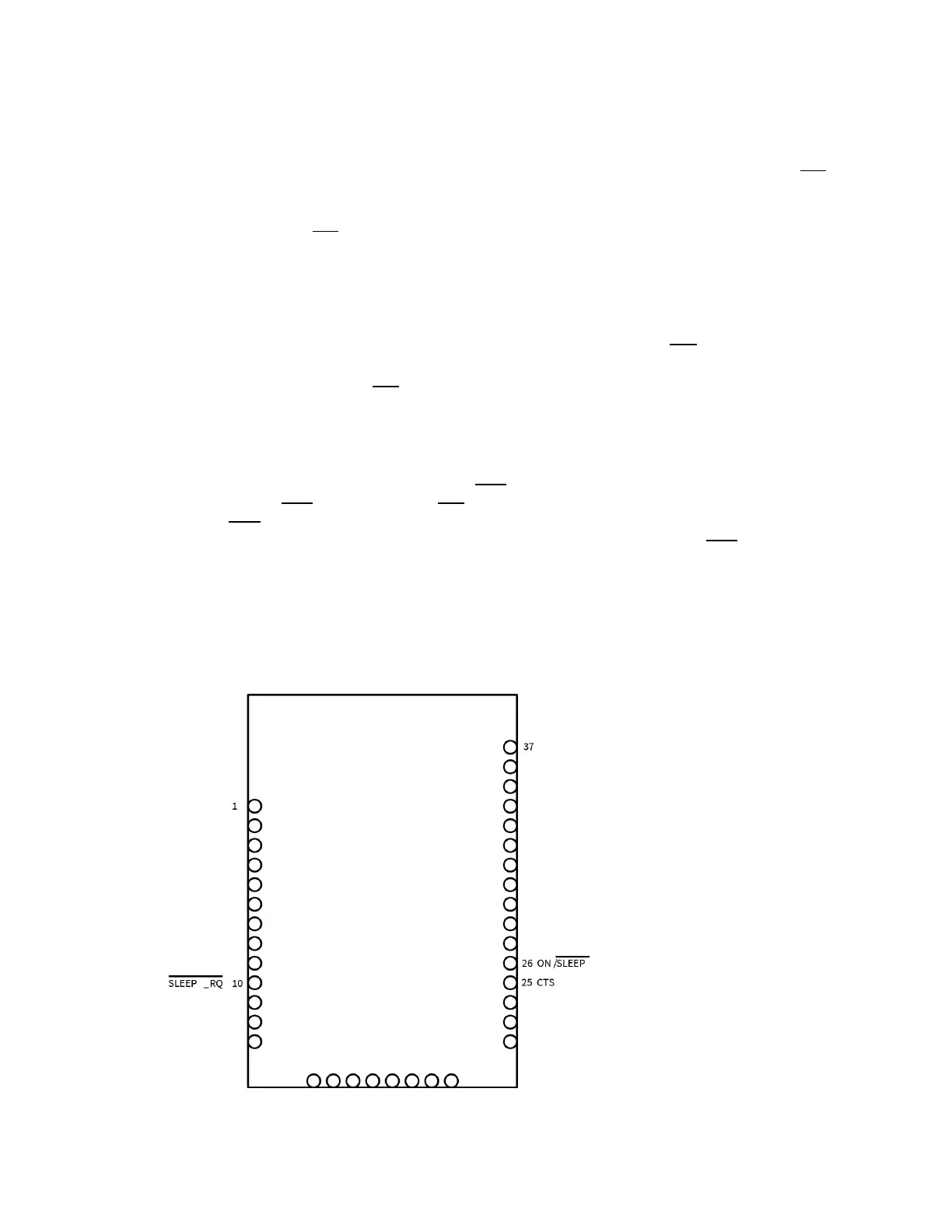
Sleep pin diagrams
The following figures show the device's sleep pins.
Surface-mount sleep pins