I/O support I/O behavior during sleep
Digi XBee® 3 Zigbee® RF Module
175
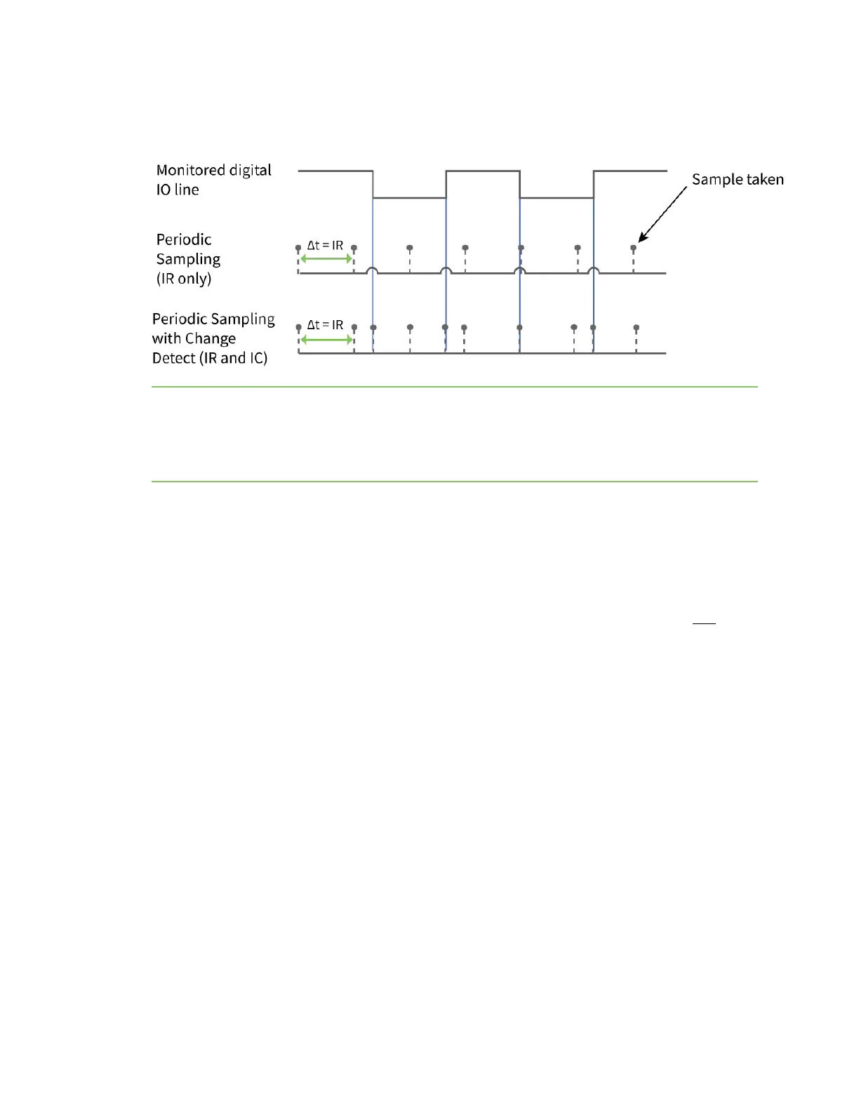
the bottom graph shows a combination ofIRperiodic samples andICdetected changes. In the top
graph, the humps indicate that the sample was not taken at that exact moment and needed to wait
for the nextIRsample period.
Note Use caution when combining change detect sampling with sleep modes.IC only causes a sample
to be generated if a state change occurs during a wake period. If the device is sleeping when the
digital transition occurs, then no change is detected and an I/O sample is not generated.
Use periodic sampling withIRin conjunction withICin this instance, sinceIRgenerates an I/O sample
upon wakeup and ensures that the change is properly observed.
I/O behavior during sleep
When the device sleeps (SM ! = 0) the I/O lines are optimized for a minimal sleep current.
Digital I/O lines
Digital I/O lines set as digital output high or low maintain those values during sleep. Disabled or input
pins continue to be controlled by the PR/PD settings. Peripheral pins (with the exception of CTS) are
set low during sleep and SPI pins are set high. Peripheral and SPI pins resume normal operation upon
wake.
Digital I/O lines that have been set using I/O line passing hold their values during sleep, however the
digital timeout timer (T0 through T9, and Q0 through Q2) are suspended during sleep and resume
upon wake.
Analog and PWM I/O Lines
Lines configured as analog inputs or PWM output are not affected during sleep. PWM lines are shut
down (set low) during sleep and resume normal operation upon wake.
PWM output pins set by analog line passing are shutdown during sleep and revert to their preset
values (M0 and M1) on wake. This happens regardless of whether the timeout has expired or not.