I/O support Periodic I/O sampling
Digi XBee® 3 Zigbee® RF Module
174
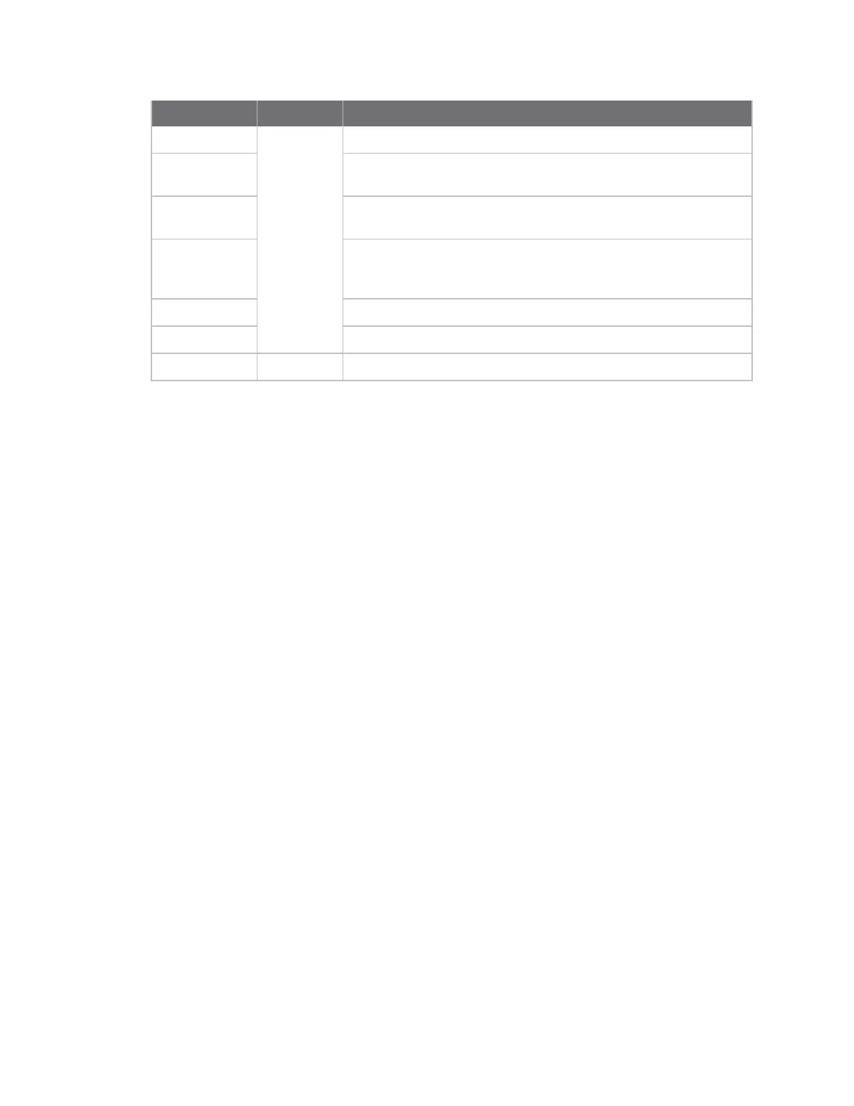
Output Field Description
01
I/O sample
data
One sample set
0C 0C Digital channel mask, indicates which digital lines are sampled
(0x0C0C = 00001100 00001100b = DIO2, 3, 10, 11)
03 Analog channel mask, indicates which analog lines are sampled
(0x03 = 0000 0011b = AD0, 1)
04 08 Digital sample data that corresponds with the digital channel mask
0x0408 = 00000100 00001000b = DIO3 and DIO10 are high, DIO2
and DIO11 are low
03 D0 Analog sample data for AD0
01 24 Analog sample data for AD1
50 Checksum Can safely be discarded on received frames
Periodic I/O sampling
Periodic sampling allows a device to take an I/O sample and transmit it to a remote device at a
periodic rate.
Source
Use IR (I/O Sample Rate) to set the periodic sample rate for enabled I/O lines.
n To disable periodic sampling, setIRto0.
n For all otherIRvalues, the device samples data whenIRmilliseconds elapse and transmits the
sampled data to the destination address.
TheDH (Destination Address High)andDL (Destination Address Low)commands determine the
destination address of the I/O samples.You must configure at least one pin as a digital I/O or ADC
input on the sending node to generate sample data.
Destination
If the receiving device is operating in API operating mode the I/O data sample is emitted out of the
serial port. Devices that are in Transparent operating mode discard the I/O data samples they receive
unless you enable line passing.
Digital I/O change detection
You can configure devices to transmit a data sample immediately whenever a monitored digital I/O
pin changes state. IC (Digital Change Detection) is a bitmask that determines which digital I/O lines to
monitor for a state change. If you set one or more bits inIC, the device transmits an I/O sample as
soon it observes a state change on the monitored digital I/O line(s) using edge detection.
Change detection is only applicable to digital I/O pins that are configured as digital input (3) or digital
output (4 or 5).
The figure below shows how I/O change detection can work in combination with Periodic I/O
sampling to improve sampling accuracy.In the figure, the gray dashed lines with a dot on top
represent samples taken from the monitored DIO line. The top graph shows only periodicIRsamples,