Frame descriptions I/O Data Sample Rx Indicator frame - 0x92
Digi XBee® 3 Zigbee® RF Module
296
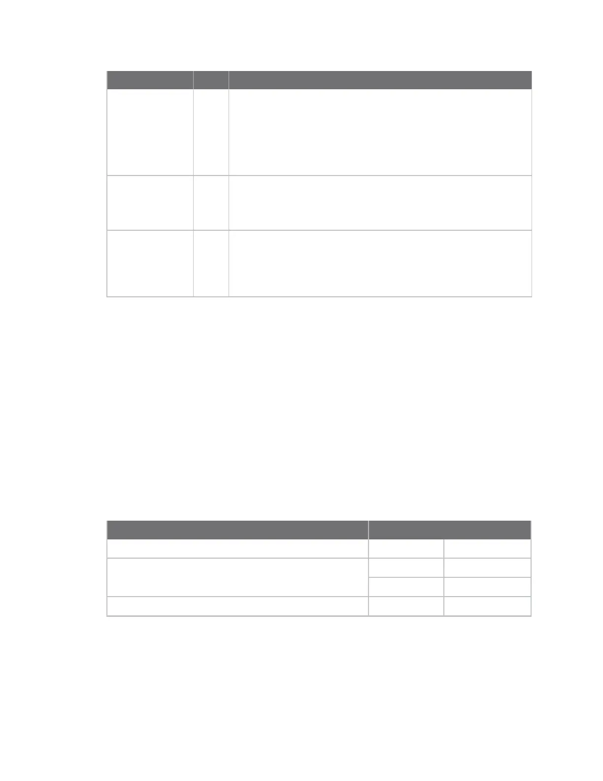
Framedatafields Offset Description
Analog channel
mask
18
Bitmask field that indicates which analog I/O lines on the remote have
sampling enabled, if any.
bit 0 = AD0/DIO0
bit 1 = AD1/DIO1
bit 2 = AD2/DIO2
bit 3 = AD3/DIO3
bit 7 = Supply Voltage (enabled with V+ command)
Digital samples (if
included)
19-20
If the sample set includes any digital I/Olines (Digital channel mask >
0), these two bytes contain samples for all enabled digital I/O lines.
DIO lines that do not have sampling enabled return 0. Bits in these two
bytes map the same as they do in the Digital channel mask field.
Analog samples (if
included)
21-n If the sample set includes any analog I/Olines (Analog channel mask >
0), each enabled analog input returns a 2-byte value indicating the A/D
measurement of that input. Analog samples are ordered sequentially
from ADO/DIO0 to AD3/DIO3 and will optionally include supply voltage
if enabled with the
V+
command.
Example
In this example, the device receives an I/O sample with analog and digital input from a remove device
with a 64-bit serial number of 0x0013A20040522BAA and a 16-bit address of 0x7D84.
Given this frame, the following information is known about the I/O lines of the module that sent the
sample frame:
Digital Channel Mask:
0x1C = 11100b (DIO2, DIO3, DIO4 are configured as digital input or output)
Digital Sample:
0x14 = 10100b (DIO2 and DIO4 are high, DIO3 is low)
Analog Channel Mask:
0x02 = 0010b (AD1 is configured as an analog input)
Analog Sample:
0x0225 = 549 = (549 * 1.25) / 1023 = 670 mV
Frame fields Offset Example
Start delimiter 0 0x7E
Length MSB 1 0x00
LSB 2 0x14
Frame type 3 0x92