C. Theory of Operation
72A-2570-01 Rev. K 07/2011 C-3
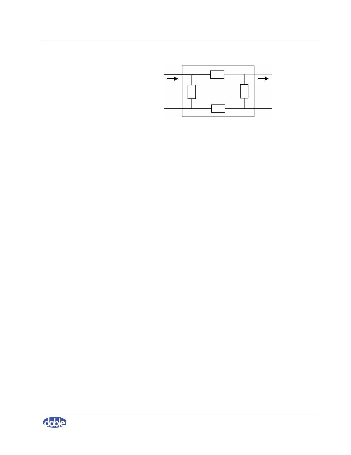
Figure C-1 Two-Port Network
Solving for the open-circuit impedance for each lumped element forms the
impedances Z11, Z22, Z12, and Z21. It should be noted that the negative
terminals are short- circuited when transformers are tested. The transformer tank
is common for both negative and lower terminals. The transformer tank and lead
ground shields must be connected together to achieve a common-mode
measurement. This assures that no external impedance is measured. Applying the
connection in this manner helps reduce the effects of noise. It is important to
obtain a zero impedance between the lower or negative terminals to assure a
repeatable measurement.
The transfer function of an RLC network is the ratio of the output and input
frequency responses when the initial conditions of the network are zero. Both
magnitude and phase relationships can be extracted from the transfer function.
The transfer function helps us better understand the input/output relationship of a
linear network. The transfer function also represents the fundamental
characteristics of a network and is a useful tool in modeling such a system.
The transfer function is represented in the frequency domain and is denoted by the
Fourier variable H(j
), where (j) denotes the presence of a frequency-dependent
function, and
= 2f. The Fourier relationship for the input/output transfer
function is given by:
When a transfer function is reduced to its simplest form, it generates a ratio of two
polynomials. The main characteristics, such as half-power and resonance, of a
transfer function occur at the roots of the polynomials.
The goal of SFRA is to measure the impedance model of the test specimen. When
we measure the transfer function H(j
), it does not isolate the true specimen
impedance
Z(j
). The true specimen impedance Z(j) is the RLC network, which is
positioned between the instrument leads, and it does not include any impedance
supplied by the test instrument.
++
––
Z
12
Z
22
Z
21
Z
11
I
in
V
in
I
out
V
out
Hj
V
output
j
()
V
input
j
()
----------------------------=