3. Setting Up and Running a Test
72A-2570-01 Rev. K 07/2011 3-25
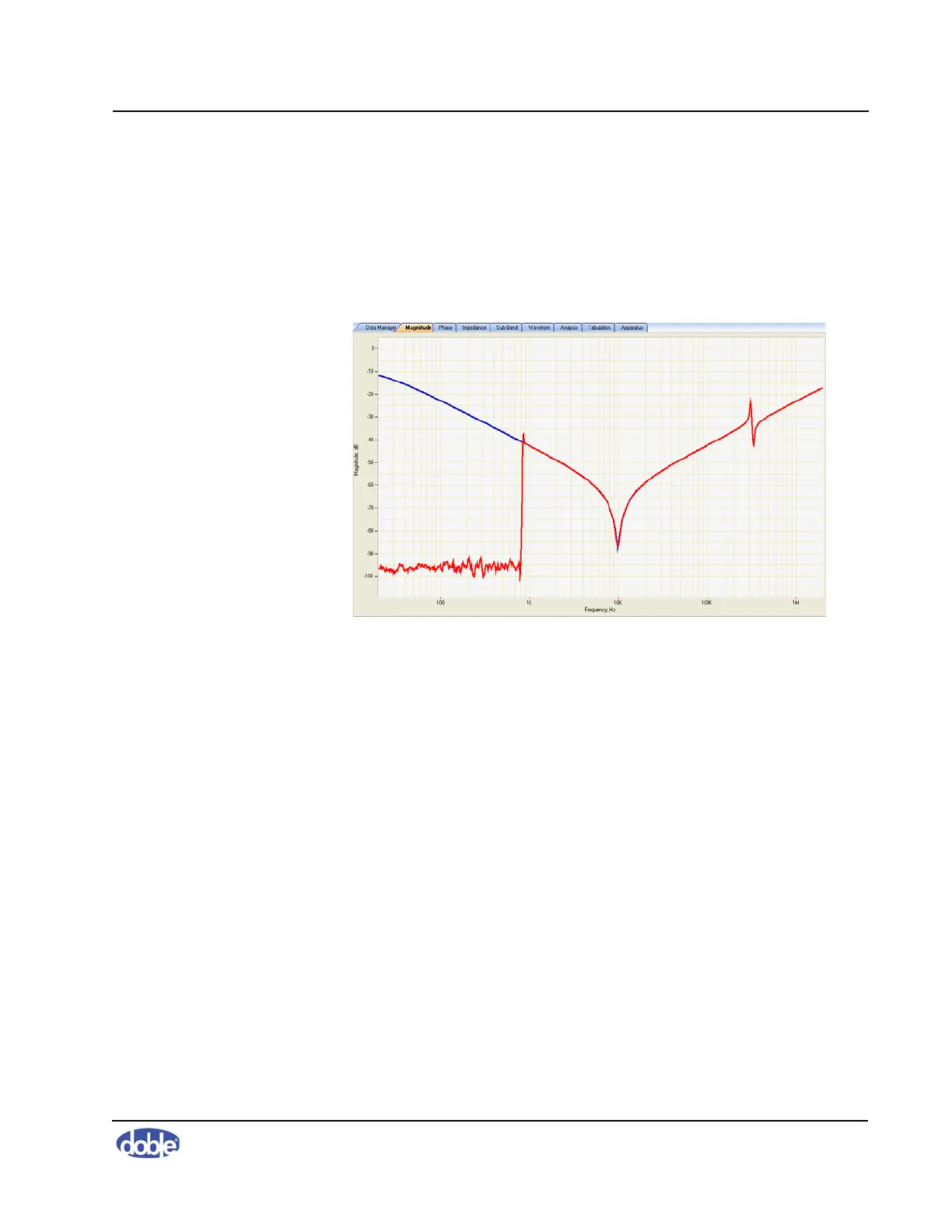
Diagnosing Open-Circuit Response
An open-circuit response may be caused by the black test lead dropping off the
bushing, a poor connection, or damage within the test lead. The discrete
change in the lower frequency range in Figure 3.39 on page 3-25 shows
typical open-circuit behavior: about –90 to –100 dB. Investigate a test like this
to see if the open circuit lies in the test setup or the transformer.
Figure 3.39 Typical Open-Circuit Trace
Sample Test Results
This section provides typical results from a number of transformer windings
and designs. These are examples of how designs and phase results vary
between transformers.
Three Responses for One Transformer
Figure 3.40 on page 3-26 shows the two open-circuit responses and the
short-circuit response of one phase of an autotransformer. The three traces are
clearly different at low frequencies.
Typically, the HV response starts at a much lower level than the LV response.
The short-circuit response approaches 0 dB at low frequency but comes back
in line with the HV response at higher frequencies.