Sweep Frequency Response Analyzer (SFRA) User Guide
3-26 72A-2570-01 Rev. K 07/2011
Figure 3.40 Responses for One Phase of a Transformer HV Delta Trace
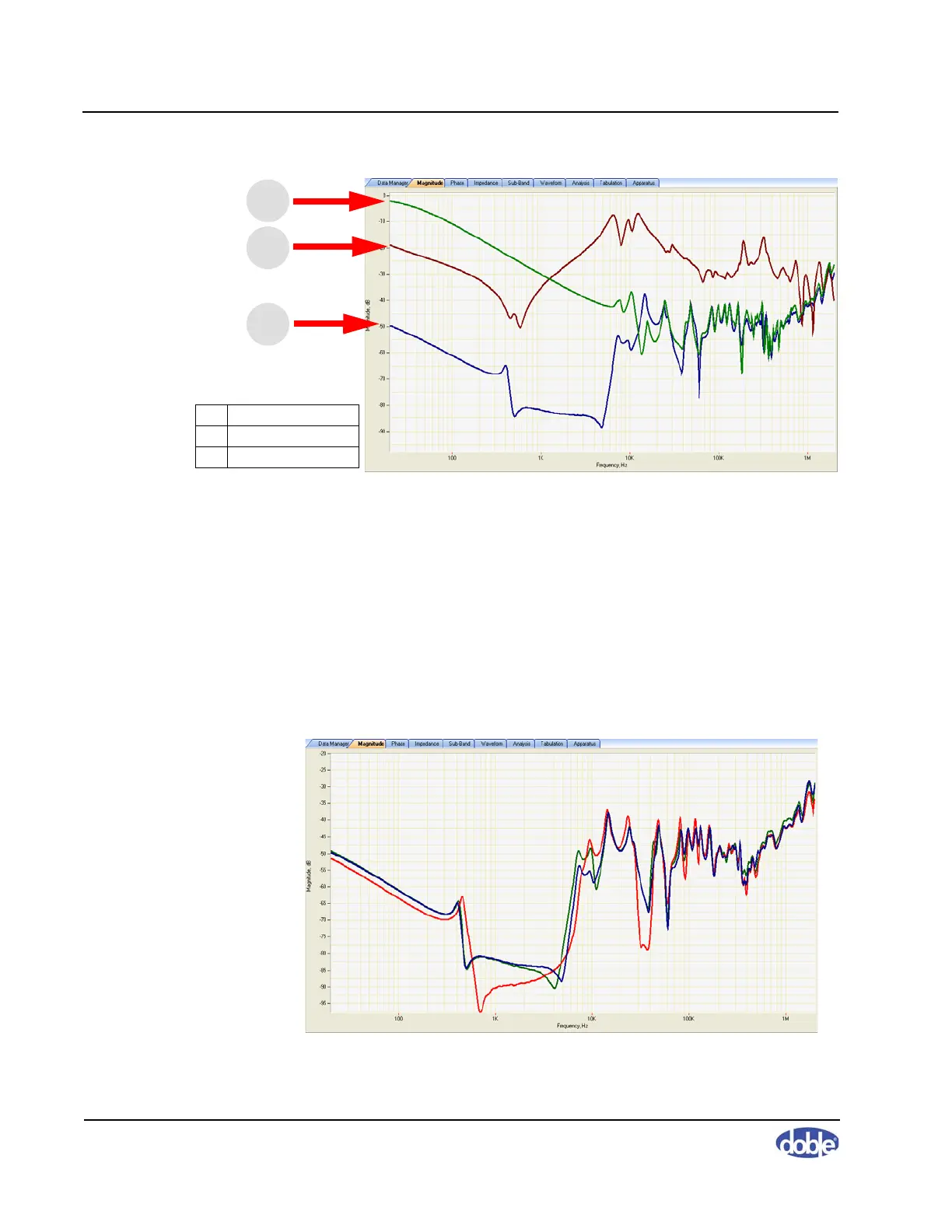
Figure 3.41 shows the responses for three phases of a HV delta winding. This
is a characteristic response at low frequencies:
• The center phase has a slightly higher impedance (more negative
response) at lower frequencies.
• The center phase is different from the outer phases at the first
resonance below 10 kHz.
• The center phase is similar to the outer phases as frequency rises.
• All three phases have the same basic shape above about 100 kHz.
Figure 3.41 HV Delta Winding Traces
1 Short Circuit
2 Open Circuit LV
3 Open Circuit HV
1
3
2