3. Setting Up and Running a Test
72A-2570-01 Rev. K 07/2011 3-9
The Test Details window appears (Figure 3.13).
Figure 3.13 Test Details Window
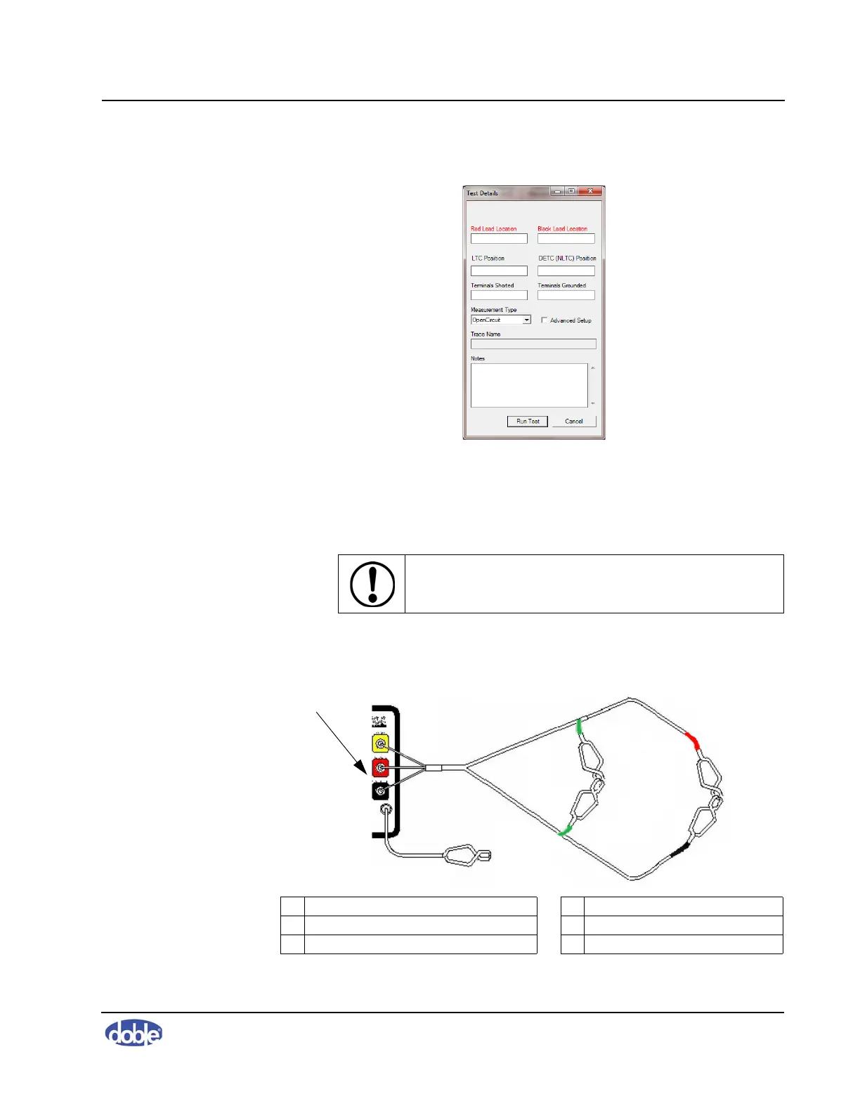
4. Short the red source lead and black measurement lead by connecting the
clamps to each other (Figure 3.14).
5. Short the green reference grounds by connecting the clamps to each other
(Figure 3.14).
Figure 3.14 Cable Connections for Shorted-lead Test
CAUTION! Do not connect the measurement clamps to
the ground clamps!
1 BNC yellow, red, and black connectors 4 Green reference ground 2 of 2
2 Instrument ground 5 Red source lead
3 Green reference ground 1 of 2 6 Black measurement lead
1
2
4
3
5
6