AssuredSAN 4004 Series Setup Guide 101
During a shutdown, the cooling fans do not shut off. This allows the enclosure to continue cooling.
Temperature sensors
Extreme high and low temperatures can cause significant damage if they go unnoticed. Each controller
module has six temperature sensors. Of these, if the CPU or FPGA (Field-programmable Gate Array)
temperature reaches a shutdown value, the controller module is automatically shut down. Each power
supply has one temperature sensor.
When a temperature fault is reported, it must be remedied as quickly as possible to avoid system damage.
This can be done by warming or cooling the installation location.
When a power supply sensor goes out of range, the Fault/ID LED illuminates amber and an event is
logged to the event log.
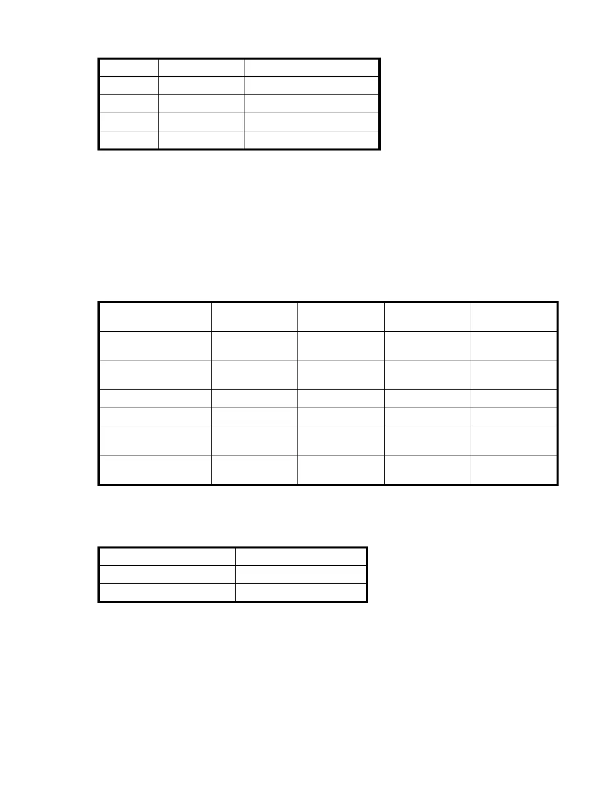
Table 34 Cooling fan sensor descriptions
Description Location Event/Fault ID LED condition
Fan 1 Power supply 1 < 4,000 RPM
Fan 2 Power supply 1 < 4,000 RPM
Fan 3 Power supply 2 < 4,000 RPM
Fan 4 Power supply 2 < 4,000 RPM
Table 35 Controller module temperature sensor descriptions
Description Normal operating
range
Warning operating
range
Critical operating
range
Shutdown values
CPU temperature 3C–88C0C–3C,
88C–90C
> 90C0C
100C
FPGA temperature 3C–97C0C–3C,
97C–100C
None 0C
105C
Onboard temperature 1 0C–70CNoneNoneNone
Onboard temperature 2 0C–70CNoneNoneNone
Onboard temperature 3
(Capacitor temperature)
0C–70CNoneNoneNone
CM temperature 5C–50C 5C,
50C
0C,
55C
None
Table 36 Power supply temperature sensor descriptions
Description Normal operating range
Power supply 1 temperature –10C–80C
Power supply 2 temperature –10C–80C