AssuredSAN 4004 Series Setup Guide 121
4U56 controller enclosures
The diagram and table below display and identify important component items that comprise the rear panel
layout of a 4U56 controller enclosure. Diagrams and tables on the following pages describe rear panel
LED behavior.
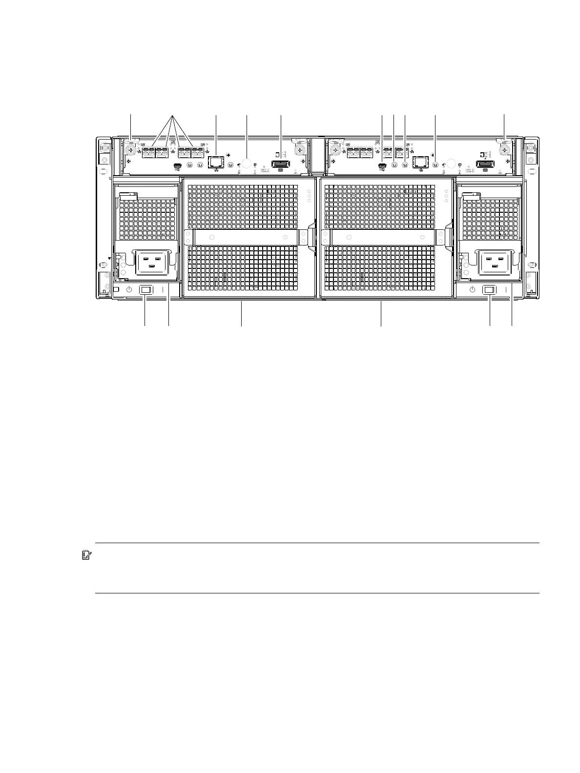
Figure 99 4004 Series controller enclosure: rear panel (4U)
The controller enclosure accommodates two controller module FRUs of the same type within the I/O
module (IOM) slots (see callouts No.1 and No.2 above). The controller enclosure accommodates two
power supply FRUs of the same type within the power supply slots (see two instances of callout No.4
above). AC PSUs are shown in the example. Beneath each power supply is a power supply switch (see two
instances of callout No.3 above). The controller enclosure accommodates two fan control modules (see two
instances of callout No.5 above).
IMPORTANT: 4U56 controller enclosures support dual-controller configuration only. Single-controller
support is provided only when a controller fails over to its partner controller. A controller module must be
installed in each IOM slot to ensure sufficient air flow through the enclosure during operation.
Figure 99 shows a 4U56 controller enclosure equipped with AC power supplies. Alternatively, the
enclosure can be equipped with redundant DC power supplies (see Figure 105 on page 126).
The diagrams with tables that immediately follow provide descriptions for the controller modules, power
supply modules, and fan control modules that can be installed into the rear panel of a 4U56 controller
enclosure. Showing them separately from the enclosure enables improved clarity in identifying the
component items called out in the diagrams and described in the tables.
Descriptions are also provided for optional drive enclosures supported by 4004 Series controller enclosures
for expanding storage capacity.
1 Controller module A
2 Controller module B
3 AC power supply switch
4 AC power supply
5 Fan control module
6 CNC ports: used for host connection or replication
7 Network port
8 Disabled button (used by engineering/test only)
(Stickers shown covering the openings)
9 SAS expansion port
10 CLI port (USB - Type B)
11 Service port 2 (used by service personnel only)
12 Reserved for future use
13 Service port 1 (used by service personnel only)
CACHE
LINK
ACT
6Gb/s
CLI
CLI
PORT 2 PORT 3
SERVICE−1SERVICE−2
PORT 0 PORT 1
CACHE
LINK
ACT
6Gb/s
CLI
CLI
PORT 2 PORT 3
SERVICE−1SERVICE−2
PORT 0 PORT 1
26 7 12 1
3 4 5 543
8 9 1110
5
13