54 Installing the enclosures
Connect power cable to 2U DC power supply
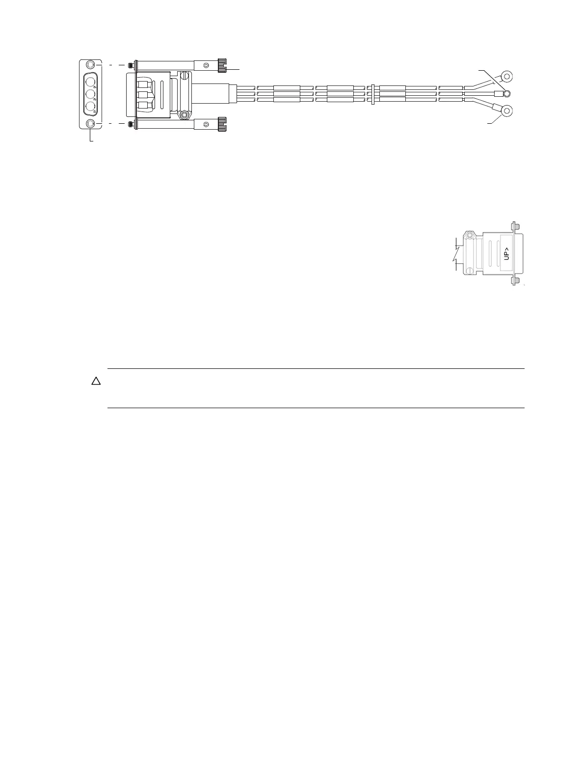
Figure 53 DC power cable featuring D-shell and lug connectors (2U)
See Figure 53 and the illustration at left (in Figure 52) when performing the following steps:
1. Locate and use the provided DC power cables.
2. Verify that the enclosure’s power switches are in the Off position.
3. Connect a DC power cable to each DC power supply using the D-shell connector.
Use the UP> arrow on the connector shell to ensure proper positioning (see
adjacent left side view of D-shell connector).
4. Tighten the screws at the top and bottom of the shell, applying a torque between 1.7
N-m (15 in-lb) and 2.3 N-m (20 in-lb), to securely attach the cable to the DC power
supply module.
5. To complete the DC connection, secure the other end of each cable wire component
of the DC power cable to the target DC power source.
Check the three individual DC cable wire labels before connecting each cable wire lug to its power
source. One cable wire is labeled ground (GND), and the other two are labeled positive (+L) and
negative (-L), respectively (shown in Figure 53 above).
CAUTION: Connecting to a DC power source outside the designated -48VDC nominal range
(-36VDC to -72VDC) may damage the enclosure.
See Power cycle on page 54.
Connect power cord to 2U48 or legacy 2U AC power supply
Obtain two suitable AC power cords: one for each AC power supply that will connect to a separate power
source. See Figure 51 on page 53 and the illustration at right in Figure 52 when performing the following
steps:
1. Verify that the enclosure’s power switches are in the Off position.
2. Identify the power cord connector on the PSU, and locate the target power source.
3. Using the AC power cords provided, plug one end of the cord into the power cord connector on the
PSU. Plug the other end of the power cord into the rack power source.
4. Verify connection of primary power cords from the rack to separate external power sources.
See Power cycle.
Power cycle
To power on the system:
1. Power up drive enclosure(s). Allow several seconds for disks to spin up.
Press the power switches at the back of each drive enclosure to the On position.
2. Power up the controller enclosure next.
Press the power switches at the back of the controller enclosure to the On position.
To power off the system:
1. Stop all I/O from hosts to the system (see Stopping I/O on page 84).
2. Shut down both controllers using either method described below:
Connector (front view)
Power cable (right side view with sectioned cutaway and wire breaks)
+L
GND
-L
+L
GND
-L
+L
GND
-L
Connector pins (typical 2 places)
Ring/lug connector (typical 3 places)
(+)
(-)
Ground