AssuredSAN 4004 Series Setup Guide 141
E SFP option for CNC ports
Locate the SFP transceivers
Locate the qualified SFP options for your CNC controller module within your product ship kit. The SFP
transceiver (SFP) should look similar to the generic SFP shown in the figure below.
Follow the guidelines
provided in Electrostatic discharge when installing an SFP.
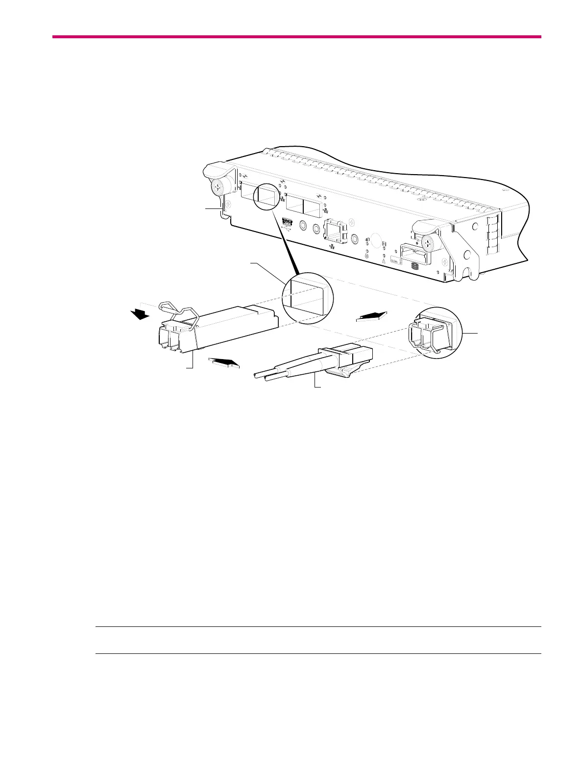
Figure 111 Install a qualified SFP option
Install an SFP transceiver
For each target CNC port, perform the following procedure to install an SFP. Refer to the figure above
when performing the steps.
1. Orient the SFP as shown above, and align it for insertion into the target CNC port.
The SFP should be positioned such that the actuator pivot-hinge is on top.
2. If the SFP has a plug, remove it before installing the transceiver. Retain the plug.
3. Flip the actuator open as shown in the figure (near the left detail view).
The actuator on your SFP option may look slightly different than the one shown, and it may not open to
a sweep greater than 90 (as shown in the figure).
4. Slide the SFP into the target CNC port until it locks into place.
5. Flip the actuator down, as indicated by the down-arrow next to the open actuator in the figure.
The installed SFP should look similar to the position shown in the right detail view.
6. When ready to attach to the host, obtain and connect a qualified fibre-optic interface cable into the
duplex jack at the end of the SFP connector.
NOTE: To remove an SFP module, perform the above steps in reverse order.
Verify component operation
View the CNC port Link Status/Link Activity LED on the controller module face plate. A green LED indicates that
the port is connected and the link is up (see LED descriptions for information about controller module LEDs).
PORT 1
CACHE
LINK
DIRTY
LINK
ACT
CLI
CLI
SERVICE−2
SERVICE−1
PORT 0
PORT 1
PO
RT 2
PORT 3
PORT 1
6Gb/s
Installed SFP
(actuator closed)
Target CNC port
Align SFP for installation
(plug removed/actuator open)
Controller module face plate
Fibre-optic interface cable