AssuredSAN 4004 Series Setup Guide 25
backend SAS expansion. See Cable requirements for storage enclosures on page 40 for cabling
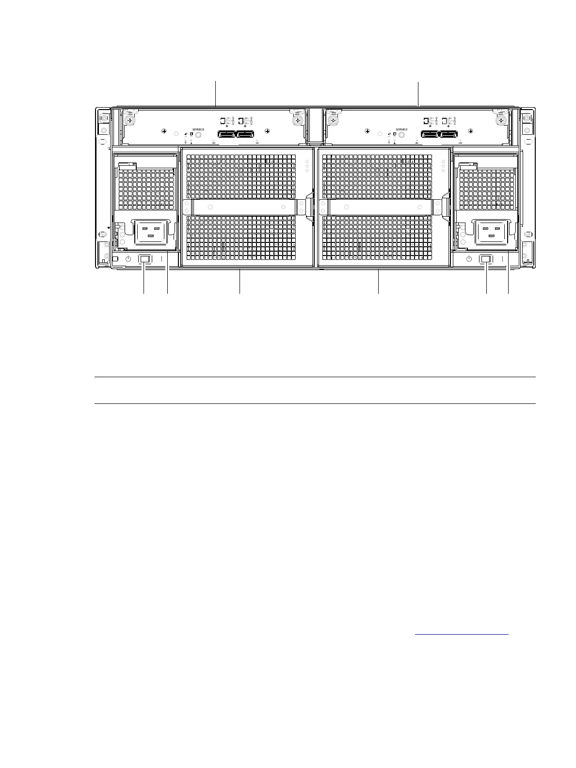
information. The example below features AC power supplies (DC not shown).
Figure 16 Drive enclosure rear panel view (4U form factor)
NOTE: See Connecting the controller enclosure and drive enclosures on page 38 for more information.
Component installation and replacement
Installation and replacement of 4004 Series FRUs (field-replaceable units) is addressed in the AssuredSAN
4004 Series FRU Installation and Replacement Guide within the “Procedures” chapter.
FRU procedures facilitate replacement of a damaged chassis or chassis component:
• Replacing a controller or expansion module
• Replacing a disk drive module
• Replacing a power supply unit (AC and DC units with integrated cooling fans)
• Replacing a fan control module (4U56)
• Replacing ear components
• Replacing a Fibre Channel transceiver
• Replacing a 10GbE SFP+ transceiver
• Replacing a 1 Gb SFP transceiver
• Replacing a controller enclosure chassis
See Dot Hill’s Customer Resource Center web site for additional information: https://crc.dothill.com
.
1 Expansion module A
2 Expansion module B
3 AC power supply switch
4 AC power supply module
5 Fan control module
0
IN OUT
6Gb/s
6Gb/s
0
0
IN OUT
6Gb/s
6Gb/s
0