116 LED descriptions
56-drive enclosure front panel LEDs
Enclosure front panel LEDs are described in two interrelated figure/table ensembles within this subsection:
• Figure 95: describes enclosure front panel LEDs (visible with the bezel installed).
• Figure 96 on page 117: describes drawer panel LEDs (visible with the bezel removed).
Disk module LEDs are described in another related figure/table ensemble within Disk drive LEDs (4U56):
• Figure 97 on page 118: describes the LEDs located on disk modules (visible with the bezel removed
and drawer(s) opened).
• Table 42 and Table 43 on page 119 describe additional disk LED behavior.
LEDs visible with enclosure bezel installed
The LEDs located on the chassis ears are described in Figure 95 and are visible with the enclosure bezel
installed.
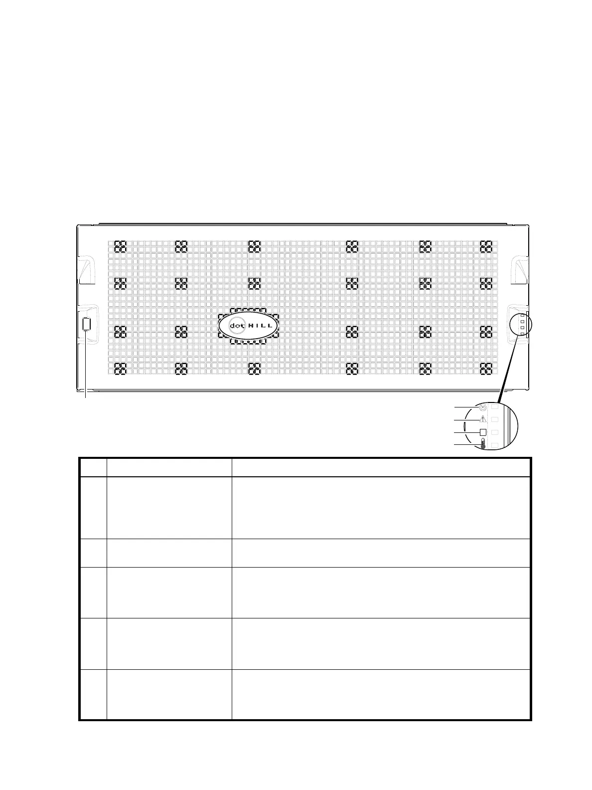
Figure 95 LEDs: 4U56 enclosure front panel
2
3
4
5
Note: Remove this enclosure bezel to access the front panel components shown below.
1
LED Description Definition
1 Enclosure ID Green — On
Enables you to correlate the enclosure with logical views presented by
management software. Sequential enclosure ID numbering of controller
enclosures begins with the integer 0. The enclosure ID for an attached drive
enclosure is nonzero.
2 Unit Locator White blink — Enclosure is identified
Off — Normal operation
3 Fault/Service Required Amber — On
Enclosure-level fault condition exists. The event has been acknowledged but
the problem needs attention.
Off — No fault condition exists.
4 FRU OK Green — On
The enclosure is powered on with at least one power supply operating
normally.
Off — Both power supplies are off; the system is powered off.
5 Temperature Fault Green — On
The enclosure temperature is normal.
Amber — On
The enclosure temperature is above threshold.