36 Installing the enclosures
2. Verify that you have inserted the disk module into the slot as far as it will go, to ensure that the module
is firmly seated in the drawer PCBA and latched in place.
IMPORTANT:
If you are completely filling a drawer with disk modules, populate from back row to front
row, while installing disks into slots. Provide adequate support for the weight of the extended drawer as
you install the disks.
If you are installing disk modules to partially fill a drawer, you must install a minimum of 14 disk modules, and
they must be placed in contiguous slots closest to the front of the drawer.
Removing a disk module from a 4U28 drawer
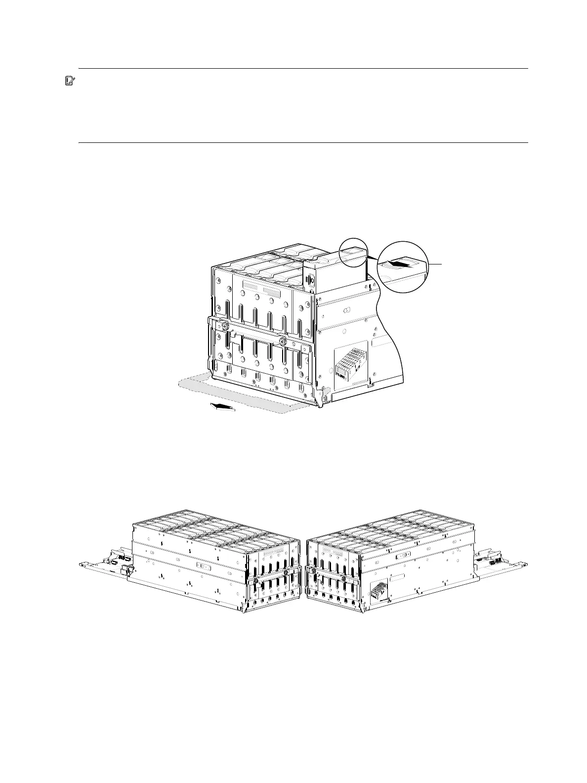
1. Using your index finger, slide the release latch—located in the right pocket on the face of the disk drive
module—to the left to disengage the disk drive module (see detail inset view in Figure 31).
Moving the latch to the left will provide a clicking sound and cause the spring to move its position
inside the drawer cage, partially ejecting the disk from its installed position within the disk drive slot.
Figure 31 Remove a disk from a drawer slot (4U56)
2. Wait 20 seconds for the internal disk to stop spinning (disk LED should illuminate blue).
3. Once the disk drive module partially ejects from the slot, grasp the module firmly, and carefully pull it
straight out of the drawer slot. Take care not to drop the module.
Examples of fully-populated drawers are shown below as isolated sub-assembly pictorials.
Figure 32 Drawer 0 with full complement of disks (4U56)
The complementary views of the left drawer (Figure 32) and right drawer (Figure 33 on page 37) viewed
from front bird’s-eye orientation show key characteristics of the drawers, including a) staggered elevation of
slide rails, b) locations of applied drawer row/slot-numbering reference diagrams, and c) orientation of
installed disk modules.