104 LED descriptions
Enclosure bezel attachment and removal
When you initially attach or remove the front panel enclosure bezel for the first time, refer to the
appropriate pictorials for your enclosure(s) from the list below, and follow the instructions provided.
• Front view of 24-drive enclosure (2U24): Figure 80 on page 103
• Front view of 12-drive enclosure (2U12) or 48-drive enclosure (2U48): Figure 81 on page 103
• Front view of 56-drive enclosure (4U56): Figure 82 on page 103
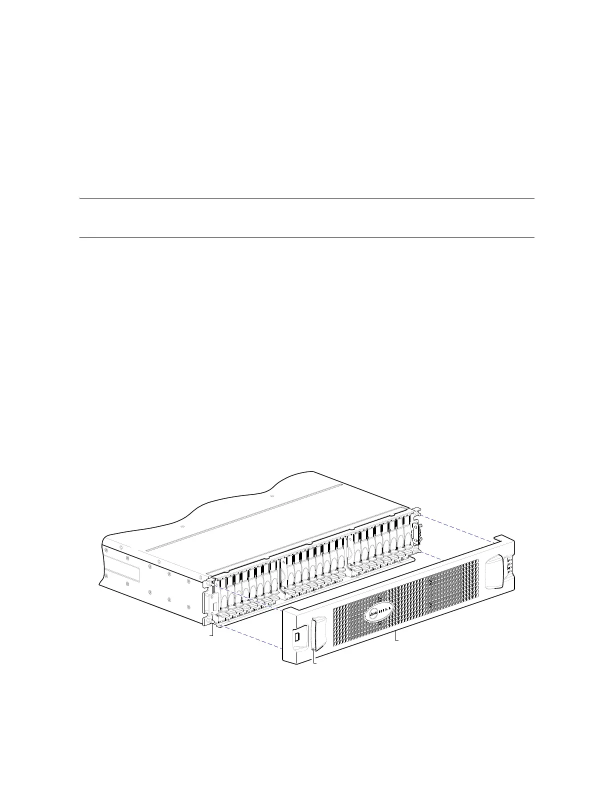
• Bezel alignment for 24-drive enclosure (2U24): Figure 83 on page 104
• Bezel alignment for 12-drive enclosure (2U12): Figure 84 on page 105
• Bezel alignment for 48-drive enclosure (2U48): Figure 85 on page 105
• Bezel alignment for 56-drive enclosure (4U56): Figure 87 on page 106
NOTE: Step procedures for attaching and removing enclosure bezels are also provided in the
AssuredSAN 4004 Series FRU Installation and Replacement Guide.
Enclosure bezel attachment
2U—Orient the enclosure bezel to align its back side with the front face of the enclosure as shown in
Figure 83 on page 104, Figure 84 on page 105, and Figure 85 on page 105. Face the front of the
enclosure, and while supporting the base of the bezel, position it such that the mounting sleeves within the
integrated ear caps align with the ball studs, and then gently push-fit the bezel onto the ball studs to
securely attach the bezel to the front of the enclosure.
4U—Orient the enclosure bezel to align its back side with the front face of the enclosure as shown in
Figure 87. Tilt the bezel forward, and guide the two angle-bracket slots on the backside of the bezel onto the
two upturned flanges located on sidemount brackets near the front of the enclosure (on the exterior left and
right chassis walls). Then, gently push the sleeves onto the ball studs as shown in the details in Figure 87.
Enclosure bezel removal
2U—While facing the front of the enclosure, insert the index finger of each hand into the top of the
respective (left or right) pocket opening, and insert the middle finger of each hand into the bottom of the
respective opening, with thumbs on the bottom of the bezel face. Gently pull the top of the bezel while
applying slight inward pressure below, to release the bezel from the ball studs.
Figure 83 Partial assembly showing bezel alignment with 2U24 chassis
Ball stud on chassis ear
(typical 4 places)
Enclosure bezel
Pocket opening (typical 2 places)