126 LED descriptions
2U48 AC power supplies have a power switch. Power supplies are used by controller and drive enclosures.
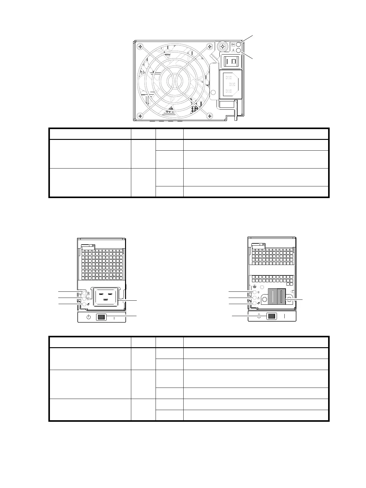
Figure 104 LEDs: Power supply units — rear panel (2U48)
The AC PSU illustration within Figure 105 employs a partial or broken section on the plastic protection
guard in order to show the underlying LED icons next to the PSU LEDs.
Figure 105 LEDs: Power supply units — rear panel (4U56)
LED No./Description Color State Definition
1 — Input Source Power Good Green On Power is on and input voltage is normal.
Off Power is off, or input voltage is below the minimum
threshold.
2 — Voltage/Fan Fault/Service
Required
Amber On Output voltage is out of range, or a fan is operating below
the minimum required RPM.
Off Output voltage is normal.
1
2
3
Power supply switch (chassis-mounted)
1
2
3
AC power connect
DC power
connect
AC model DC model
LED No./Description Color State Definition
1 — AC Input Source Green On Power is on and input voltage is normal.
Off No AC input to PSU.
2 — Voltage/Fan Fault/Service
Required
Amber On
Blinking
Output voltage is out of range, or a fan is operating below
the minimum required RPM.
Off Fault not detected.
3 — DC Power Green On Main output power on.
Off Power is off; main output is off; or a fault is detected.