56 Installing the enclosures
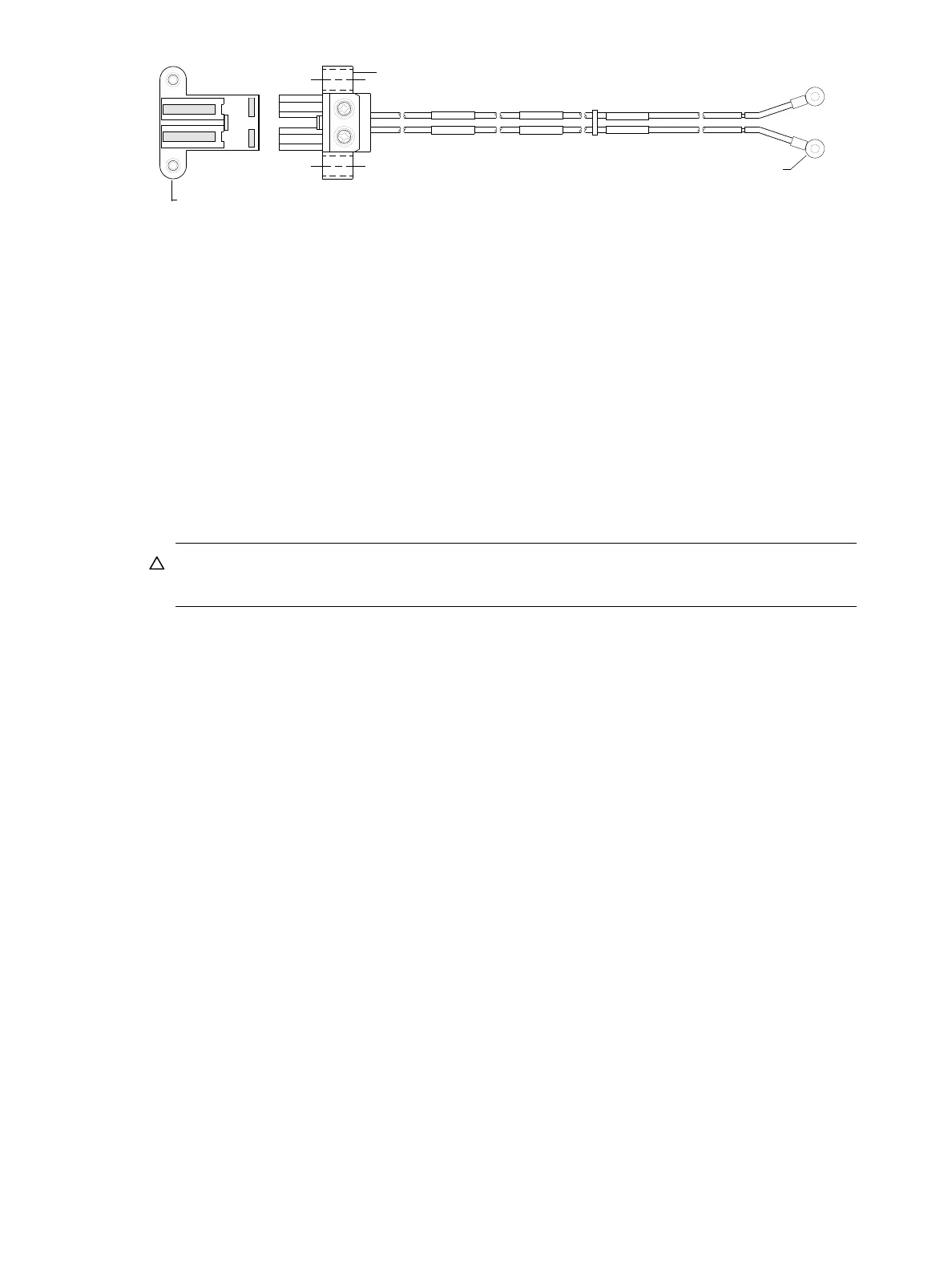
Figure 56 DC power cable featuring 2-circuit header and lug connectors (4U)
See Figure 55 and Figure 56 when performing the following steps:
1. Locate the appropriate DC power cables.
2. Verify that the enclosure’s power switches are in the Standby position.
3. Connect the DC power to each DC power supply using the 2-circuit header connector.
4. Tighten the screws at the base of the connector—left and right sides—applying a torque between 1.7
N-m (15 in-lb) and 2.3 N-m (20 in-lb), to securely attach the cable to the DC power supply module.
5. To complete the DC connection, secure the other end of each cable wire component of the DC power
cable to the target DC power source.
Check the two individual DC cable wire labels before connecting each cable wire lug to its power
source. One wire is labeled positive (+L) and the other is labeled negative (-L), as shown in Figure 56
on page 56. The 4004 Series enclosure is grounded independently of this DC cable. The chassis
ground wire is connected from a stud on its mounting rail to the rack in which it is mounted.
CAUTION: Connecting to a DC power source outside the designated -48VDC nominal range
(-36VDC to -72VDC) may damage the enclosure.
Power cycle
Once the system is successfully cabled, use the following procedures to power on and power off.
To power on the system:
1. Power up drive enclosure(s) by doing one of the following:
• Press the power switches at the back of each drive enclosure to the On position; or
• Connect the power cable from the power source to the connector on the PSU (switchless PSUs).
Allow 2.5 minutes for disks to spin up.
2. Power up the 4U controller enclosure next.
Press the power switches at the back of the controller enclosure to the On position.
To power off the system:
1. Stop all I/O from hosts to the system (see Stopping I/O on page 84).
2. Shut down both controllers using either method described below:
• Use the SMC or RAIDar to shut down both controllers, as described in the online help and Storage
Management Guide.
Proceed to step 3.
• Use the CLI to shut down both controllers, as described in the CLI Reference Guide.
3. Press the power switches at the back of the 4U controller enclosure to the Standby position.
4. Power down drive enclosure(s) by doing one of the following:
• Press the power switches at the back of each drive enclosure to the Off position; or
• Disconnect the power cable from the power source to the connector on the PSU (switchless PSUs).
Connector (front view)
Power cable (right side view with wire breaks)
+L
-L
+L
-L
+L
-L
Connector screw (typical 2 places)
Ring/lug connector (typical 2 places)
(+)
(-)