AssuredSAN 4004 Series Setup Guide 117
NOTE: The enclosure front panel illustrations that follow assume that you have removed the enclosure
bezel to reveal underlying components.
LEDs visible with enclosure bezel removed
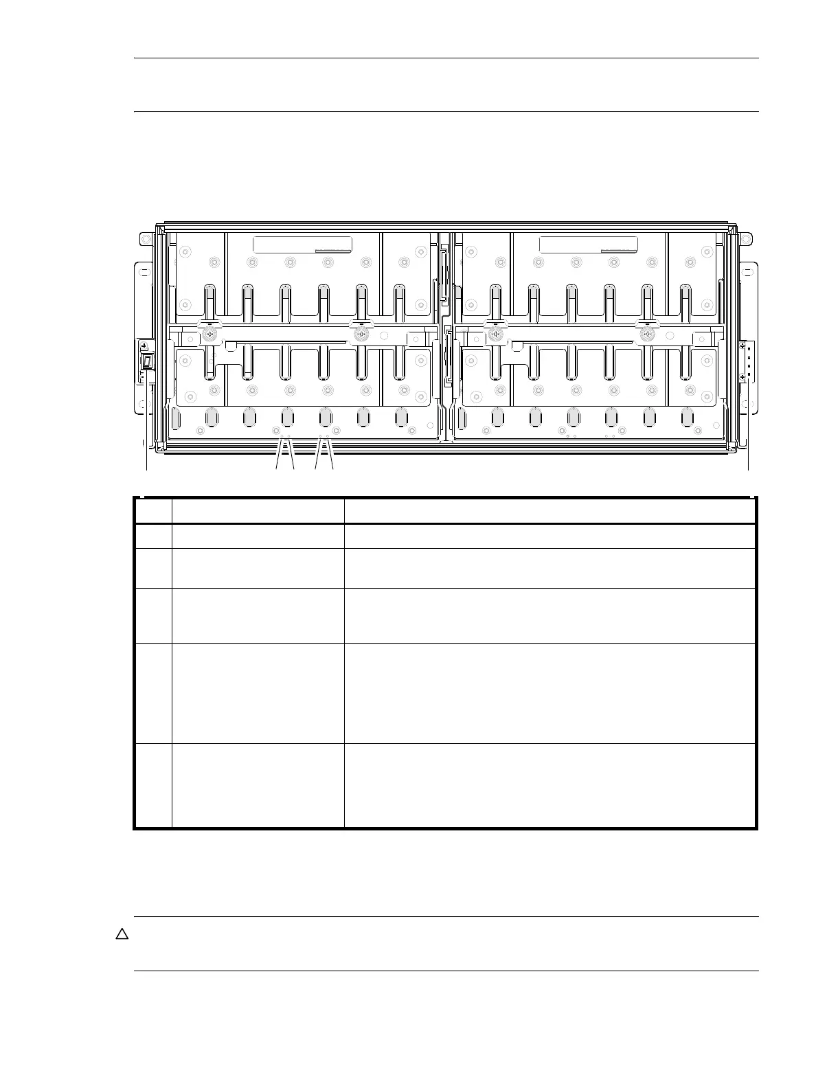
The enclosure bezel is removed to reveal the underlying 4U56 enclosure front panel LEDs. The front panel
LEDs—including ear LEDs and drawer panel LEDs—are described in the table below the illustration.
Figure 96 LEDs: 4U56 drawer front panel
The enclosure bezel for this model provides the EMI protection from the product. The bezel should be
securely attached to the enclosure during operation.
CAUTION: Whether configured with or without an air filter, to ensure adequate EMI protection from the
product, the enclosure bezel should be properly installed while the enclosure is in operation.
LED Description Definition
1 Enclosure ear LEDs Enclosure ear LEDs (see Figure 95 on page 116).
2 Unit Locator White blink — Enclosure is identified
Off — Normal operation
3 OK to Remove Blue — On
The drawer is prepared for removal.
Off — The drawer is not prepared for removal.
4 Fault/Service Required Amber — On
Drawer-level fault condition exists. The event has been acknowledged but
the problem needs attention.
Amber — Blink
Hardware-controlled power-up.
Off — No fault condition exists.
5 FRU OK Green — On
The drawer is powered on with the power supply operating normally.
Green — blink
The drawer is initializing.
Off — The drawer is not OK.
DRAWER 0
DRIVES 0 − 27
PN: 21−00000590−00−01 rev A
DRAWER 1
DRIVES 28 − 55
PN: 21−00000590−00−02 rev A
Left ear
Right ear
1 2 3 4 5 1
Note: Bezel is removed and rails are not installed in this view.