AssuredSAN 4004 Series Setup Guide 55
• Use the SMC or RAIDar to shut down both controllers, as described in the online help and Storage
Management Guide.
Proceed to step 3.
• Use the CLI to shut down both controllers, as described in the CLI Reference Guide.
3. Press the power switches at the back of the controller enclosure to the Off position.
4. Press the power switches at the back of each drive enclosure to the Off position.
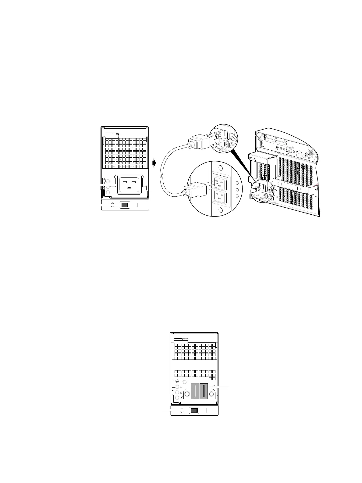
AC PSU (4U)
4004 Series 4U56 enclosures use two redundant AC PSUs, each of which is controlled by a power switch
mounted on the chassis (beneath the PSU). The illustration below shows the face of an AC power supply
module as it appears when viewing the rear panel of the 4U enclosure. Connection of the power cable to
the rack power source is also shown.
Figure 54 AC PSU with power switch (4U)
Obtain two suitable power cords: one for each AC power supply that will connect to a separate power
source. See Figure 54 when performing the following steps:
1. Verify that the enclosure’s power switches are in the Standby position.
2. Identify the power cord connector on the PSU, and locate the target power source.
3. Using the AC power cords provided, plug one end of the cord into the power cord connector on the
PSU. Plug the other end of the power cord into the rack power source.
4. Verify connection of primary power cables from the rack to separate external power sources.
DC PSU (4U)
As an alternative to using AC PSUs, the 4004 Series enclosure can use two redundant DC PSUs controlled
by the power switch mounted on the chassis.
Figure 55 DC PSU with power switch (4U)
C
AC
H
E
L
IN
K
D
IR
TY
L
I
N
K
A
C
T
C
L
I
C
LI
S
E
R
V
IC
E
−2
S
E
R
V
IC
E
−
1
P
O
R
T 0
P
O
R
T
1
P
O
R
T
2
P
O
R
T
3
6
G
b/s
Power supply
Rear panel
Rack
WARNING: NOT A LIFT POINT
cord
AC power
Power
switch
Power
cord
connect