20 Components
• See Table 3 on page 28 for sequential tasks required for successful enclosure installation.
• See Populating drawers in 4U56 enclosures on page 33 for instructions on installing disk modules.
IMPORTANT: Disk drive slot numbering is also provided on the label attached to the sheet metal housing
(side face) on each drawer. Refer to the drawer label when installing disks into the drawer.
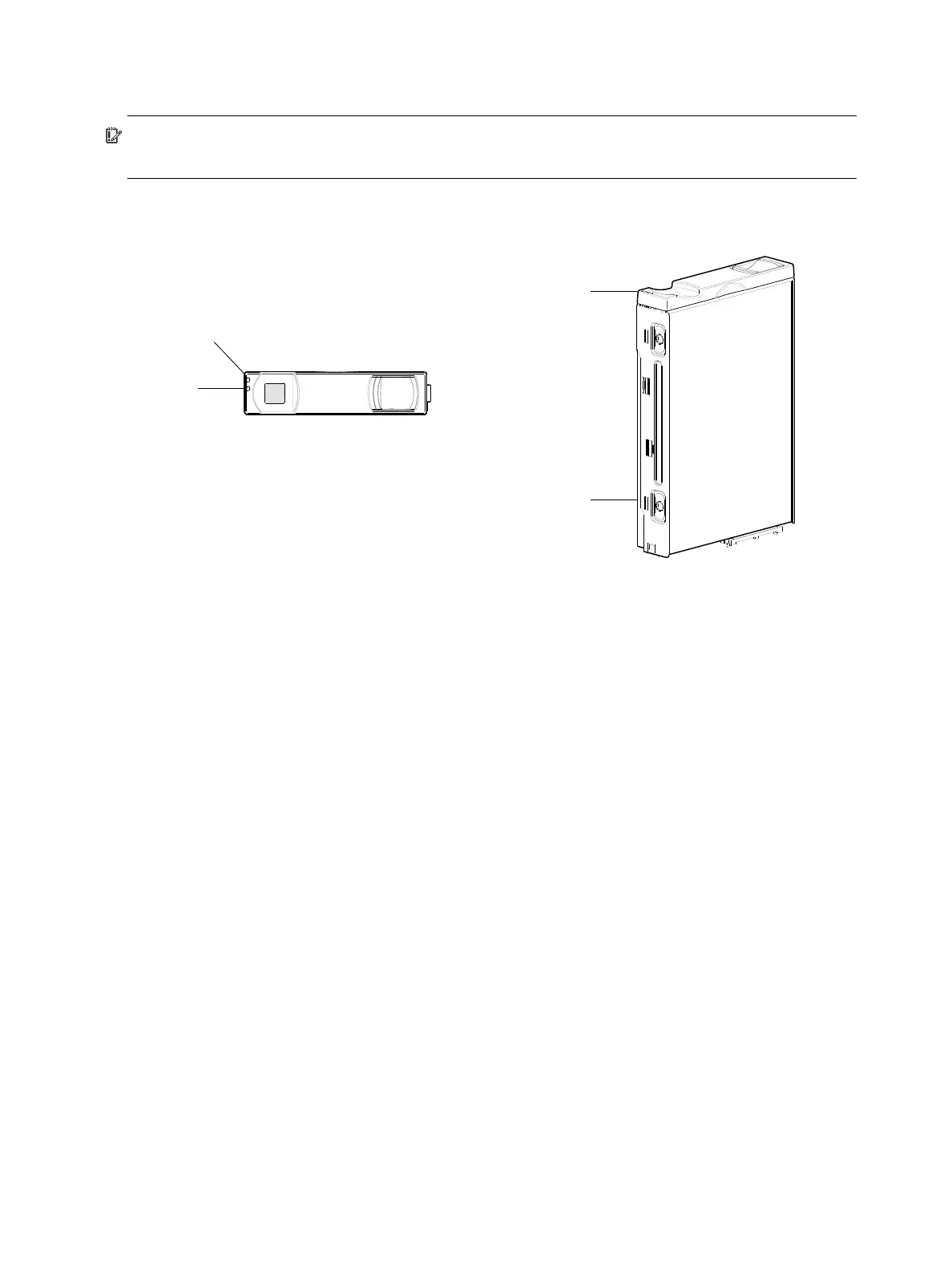
Figure 9 below provides two different view orientations of the disk drive module used in 4U56 enclosures.
Figure 9 4U56 disk drive module
Disk drives used in 4004 Series enclosures
4004 Series enclosures support LFF/SFF Midline SAS, LFF/SFF Enterprise SAS, and SFF SSD disks. They
also support LFF/SFF Midline SAS and LFF/SFF Enterprise self-encrypting disks that work with the Full Disk
Encryption (FDE) feature. For information about creating disk groups and adding spares using different
disk drive types, see the AssuredSAN Storage Management Guide or online help. Also see FDE
considerations on page 37.
Controller enclosure — rear panel layout
2U48/2U24/2U12 controller enclosures
The diagram and table below display and identify important component items that comprise the rear panel
layout of a 2U form factor AssuredSAN 4004 Series controller enclosure. The 4824/4834 is shown as a
representative example of controller enclosure models included in the product series. The rear panel layout
generally applies to the 2U48, 2U24, and 2U12 form factors. Notable differences are listed:
• Whereas the AC power supplies used in 2U24 and 2U12 enclosures are not equipped with a power
switch, the AC power supply used in 2U48 enclosures provides a power switch.
• Whereas the 2U24 and 2U12 enclosures can be configured with redundant AC power supplies or
redundant DC power supplies, the 2U48 enclosure supports redundant AC power supplies exclusively.
• Whereas the 2U24 and 2U12 enclosures support single and dual-IOM configuration, the 2U48
enclosure supports dual-IOM configuration exclusively. Single controller support is provided only when
a controller fails over to its partner controller on 2U48 enclosures.
1 3.5" sledded disk module assembly (front view)
2 Disk drive status LEDs
3 3.5" disk module aligned for insertion into drawer
(AMS inserts are not used in blank disk slots)
3.5" LFF disk drive module
(see table below for LED behaviors)
1
LEDs
2
Electromagnetic interference protection is provided by the EMI shield in the enclosure bezel.
Front view of sledded-disk
Disk module oriented for insertion into drawer
(PCBA connector is visible at base of module)