AssuredSAN 4004 Series Setup Guide 23
4824/4834/4844/4854 CNC controller module — rear panel components
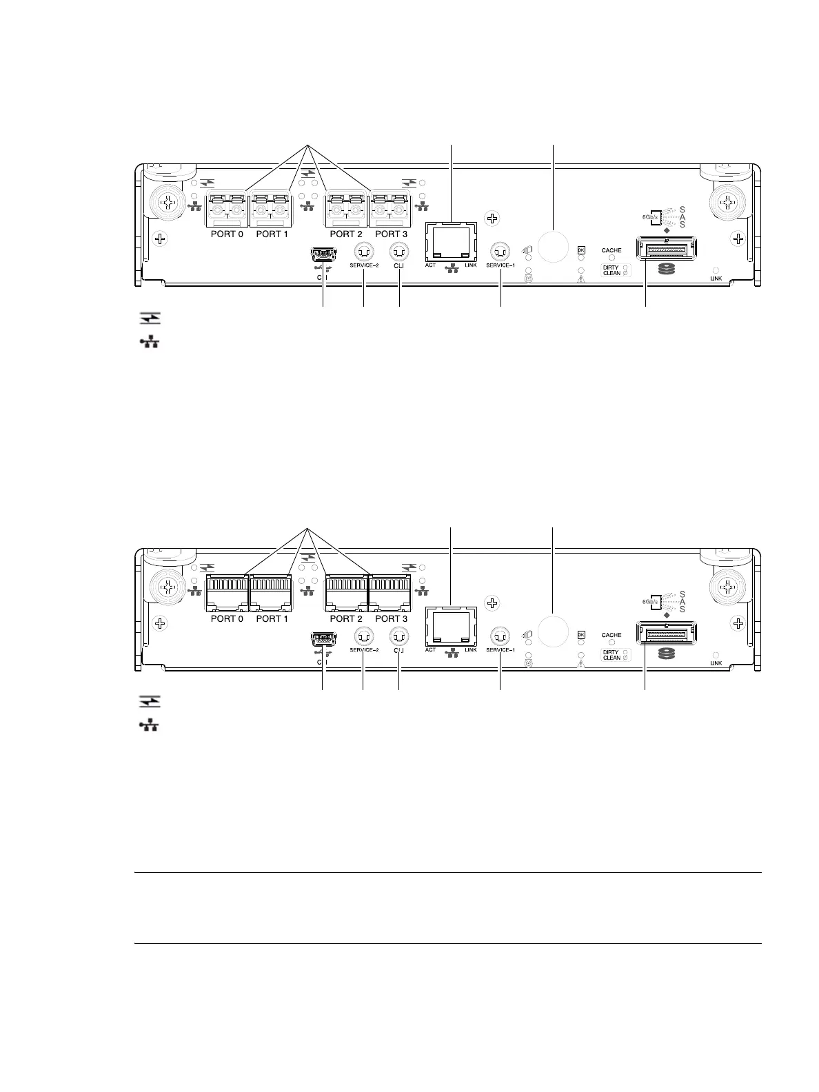
Figure 12 shows CNC ports configured with SFPs supporting either 4/8/16 Gb FC or 10GbE iSCSI. The
SFPs look identical. Refer to the CNC LEDs that apply to the specific configuration of your CNC ports.
Figure 12 4824/4834/4844/4854 controller module face plate (FC or 10GbE iSCSI)
Figure 13 shows CNC ports configured with 1 Gb RJ-45 SFPs.
Figure 13 4824/4834/4844/4854 controller module face plate (1 Gb RJ-45)
NOTE: See CNC ports used for host connection on page 11 for more information about CNC technology. For
CNC port configuration, see the “Configuring host ports” topic within the Storage Management Guide or
online help.
1 CNC ports used for host connection or replication
(see Install an SFP transceiver on page 141)
2 CLI port (USB - Type B) [see Appendix D]
3 Service port 2 (used by service personnel only)
4 Reserved for future use
5 Network port
6 Service port 1 (used by service personnel only)
7 Disabled button (used by engineering only)
(Sticker shown covering the opening)
8 mini-SAS expansion port
5
2 3 6 8
1
7
4
= FC LEDs
= 10GbE iSCSI LEDs
5
2 3 6 8
1
7
4
= FC LEDs
= 1Gb iSCSI LEDs (all CNC ports use 1 Gb RJ-45 SFPs in this figure)