AssuredSAN 4004 Series Setup Guide 49
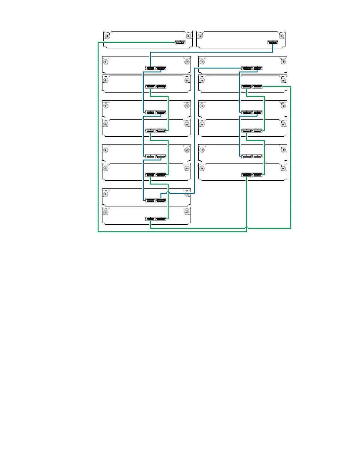
Figure 46 Reverse-cabling between a dual-controller 4U enclosure and 2U12 or 2U24 drive enclosures
Figure 46 is very similar to Figure 44 on page 48. It shows reverse cabling of maximum enclosures when
cascading either 2U12 or 2U24 drive enclosures from the 4U56 controller enclosure. In this situation, the
maximum number of supported enclosures is eight (including the controller enclosure).
Controller module 0A is connected to expansion module 1A, with a chain of connections cascading down
(blue). Controller module 0B is connected to the lower expansion module (7B), of the last expansion
enclosure, with connections moving in the opposite direction (green). Reverse cabling allows any
expansion enclosure to fail—or be removed—while maintaining access to other enclosures.
Figure 47 on page 50 shows the same storage components used in Figure 46, but they are connected
using straight-through cabling. Using this method, if an expansion enclosure fails, the enclosures that follow
the failed enclosure in the chain are no longer accessible until the failed enclosure is repaired or replaced.
Controller
enclosure
0
Drive
enclosure
In Out
Out
0B
0A
1A
1B
Controller A
Controller B
1
In
2A
2B
3A
3B
Drive
enclosure
2
Drive
enclosure
3
In Out In Out
In Out
In Out
In Out In Out
In Out In Out
Drive
enclosure
5
Drive
enclosure
6
Drive
enclosure
7
Drive
enclosure
4
4A
4B
In Out
In Out
In
Out
In Out
5A
5B
6A
6B
7A
7B