16 Components
48-drive enclosure front panel components
2U48 enclosures support
dual-IOM configuration, and are equipped with two redundant AC power supply
modules. Each AC PSU is equipped with a power switch (see Figure 104
on page 126
).
When the enclosure
bezel is installed, the 2U48 front panel looks the same as the 2U12 front panel (see the bezel, callouts,
and table entries shown in Figure 2 on page 15 for reference).
TIP: See Enclosure bezel attachment and removal on page 104 and Figure 85 on page 105 (2U48).
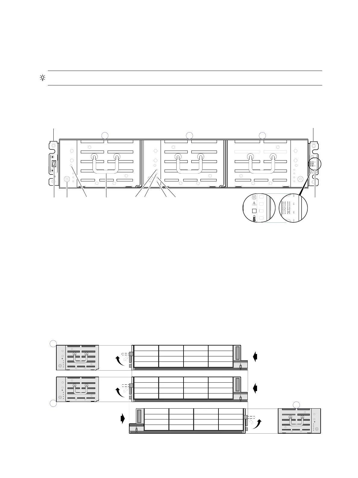
2U48 enclosure bezel removed
To access the drawers, you must remove the enclosure bezel (shown removed in Figure 3).
Figure 3 2U48 enclosure: front panel with bezel removed
2U48 enclosure drawers
You can open the enclosure drawers to access the disks. Drawers 0 and 1 provide access to disk bays from
the right side of the drawer; whereas drawer 2 provides access to disk bays from the left side of the
drawer. These respective side views—or profiles—are shown below.
Figure 4 2U48 enclosure: drawer front and side views with disk slot numbering
1 Enclosure ear LEDs/bezel (see Figure 2 on page 15)
2 Thumbscrew for securing or accessing drawer
3 Disabled button (used by engineering only)
4 Drawer handle (shown in stowed position)
5 Drawer status LED: FRU OK
6 Drawer status LED: Fault/Service Required
7 Drawer status LED: OK to Remove
8 Drawer status LED: Unit Locator
61
7
2
Left ear
Right ear
Note: Integers atop drawers indicate drawer numbering sequence.
(Silk screens on bezel)
1
4
3
5
8
Drawer Profiles
Disk bays with sequentially−numbered disk slots
Right side view
(Revolved Y −90°)
Left side view
(Revolved Y +90°)
47
46
45
44
43
42
41
40
39
38
37
36
35
34
33
32
31
30
29
28
27
26
25
24
23
22
21
20
19
18
17
16
0
1
15
14
13
12
11
10
9
8
7
6
5
4
3
2
1
0
Right side view
(Revolved Y −90°)
2