AssuredSAN 4004 Series Setup Guide 17
Your 2U48 enclosure is shipped with the drawers installed, but they are not populated with disks.
Depending on your product configuration, disk bay blanks—also known as Air Management Solution
(AMS) inserts—might be installed. Locate the box containing your sledded disks and AMS inserts (if
applicable) in preparation for populating the drive slots.
• See Table 3 on page 28 for sequential tasks required for successful enclosure installation.
• See Populating drawers in 2U48 enclosures on page 29 for instructions on installing disks and AMS
inserts.
IMPORTANT: Disk drive slot numbering is also provided on the label attached to the sheet metal housing
(top face) on each drawer. Refer to the drawer label when installing disks into the drawer.
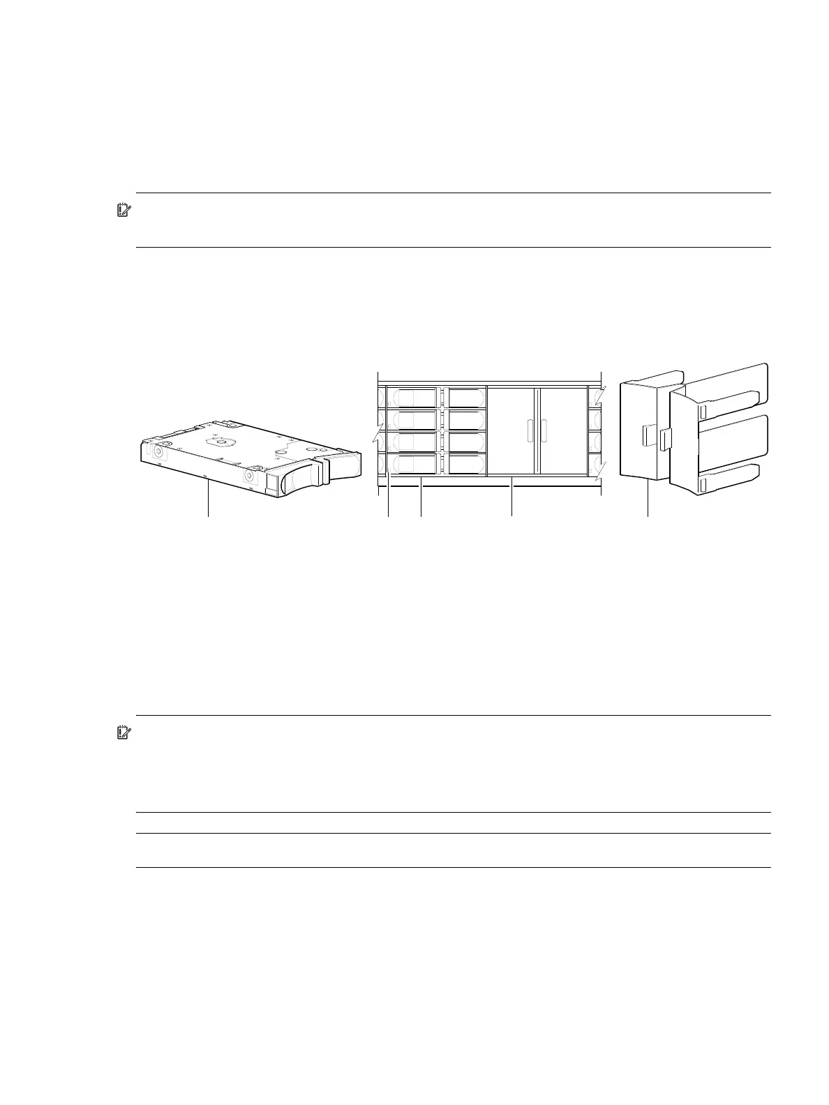
Figure 5 below provides a sample partial configuration of disk bays within a drawer. The bay on the left is
populated with four disks, whereas the adjacent bay on the right contains an AMS insert to manage air
flow within the enclosure to maintain optimal operating temperature.
1
The disk is oriented in the sled such that its PCBA faces upward on the top side of the disk drive module as shown.
2
Electromagnetic interference protection is provided by the EMI shield within the enclosure bezel.
3
The AMS insert spans an entire disk bay (4 slots). A single disk slot AMS is also available.
Figure 5 2U48 enclosure: sample drawer population
IMPORTANT: Empty bays will cause overheating. To avoid overheating, install an AMS insert in disk bays
that do not contain quantity four disk drive modules.
• Legacy models use the disk bay AMS insert shown above (spans four disk slots).
• Newer models use the single disk slot AMS insert (see Figure 24 on page 31).
NOTE: Front and rear panel LEDs for controller enclosures are described in LED descriptions.
1 2.5" sledded disk module assembly pictorial
1, 2
2 Disk drive status LED
(see Disk drive LED (2U48) on page 114)
3 2.5" disk drive module (installed in 3 of 4 disk bays)
4 Air Management Solution (AMS) insert (installed)
3
5 AMS insert pictorial
3
1 23 5
4
Disks and AMS installed in drive slots
(partial view of a 4-bay drawer)