112 LED descriptions
48-drive enclosure front panel LEDs
Enclosure front panel LEDs are described in two interrelated figure/table ensembles within this subsection:
• Figure 92: describes enclosure front panel LEDs (visible with the bezel installed).
• Figure 93 on page 113: describes drawer panel LEDs (visible with the bezel removed).
The disk module LED is described in another related figure/table ensemble within Disk drive LED (2U48):
• Figure 94 on page 114: describes the LED located on disk modules (visible with the bezel removed and
drawer(s) opened).
• Table 40 and Table 41 on page 115 describe additional disk LED behavior.
LEDs visible with enclosure bezel installed
The LEDs located on the chassis ears are described in Figure 92 and are visible with the enclosure bezel
installed.
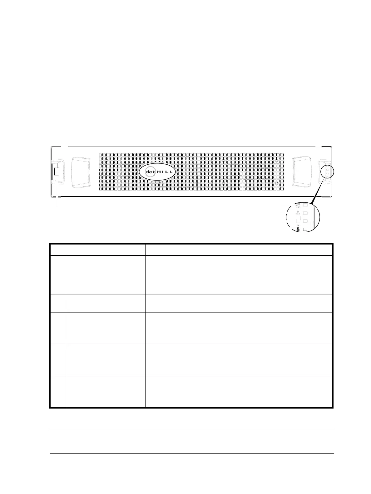
Figure 92 LEDs: 2U48 enclosure front panel
NOTE: The enclosure front panel illustrations that follow assume that you have removed the enclosure
bezel to reveal underlying components.
LED Description Definition
1 Enclosure ID Green — On
Enables you to correlate the enclosure with logical views presented by
management software. Sequential enclosure ID numbering of controller
enclosures begins with the integer 0. The enclosure ID for an attached drive
enclosure is nonzero.
2 Unit Locator White blink — Enclosure is identified
Off — Normal operation
3 Fault/Service Required Amber — On
Enclosure-level fault condition exists. The event has been acknowledged but
the problem needs attention.
Off — No fault condition exists.
4 FRU OK Green — On
The enclosure is powered on with at least one power supply operating
normally.
Off — Both power supplies are off; the system is powered off.
5 Temperature Fault Green — On
The enclosure temperature is normal.
Amber — On
The enclosure temperature is above threshold.
2
3
4
5
Note: Remove this enclosure bezel to access drawers.
1