DESCRIPTION AND INSTALLATION
2-20 25364 Issue 8 March 2018
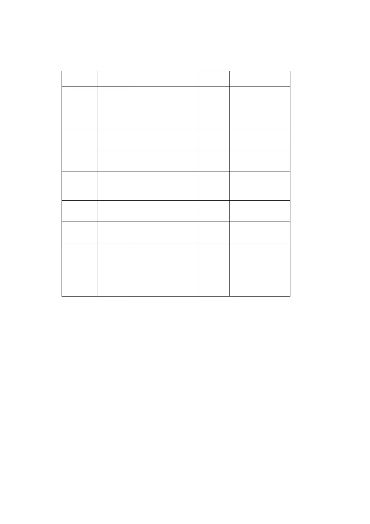
Compact 32d, 32c and 53c Pin Allocations
Name Type Default Function J3 Pins Colours
Output 1
Volt-free
contacts
Ready / Returning 4, 12
Orange - Light
Gr
een
Output 2
Volt-free
contacts
Error 3, 11 Red - Pink
Output 3
Volt-free
contacts
Warning 2, 10 Brown - White
Output 4
Powered
contact
Busy 1, 9 Black - Grey
Input 1 NPN
Encoder
(duplic
ated on
5-pin DIN)
8, 15
Purple - Red /
Whi
te
Input 2
Volt-free
contacts
Start Signal 5, 13
Yello w - Black /
Whi
te
Input 3
Volt-free
contacts
None 6, 14
Green - Brown /
Whi
te
Input 4
Volt -free
contacts
Remote Trigger
Fr
ont
Multi-Function
Button
(Function cannot
be change
d)
7, 15
Blue - Red /
Whi
te
The volt-free output contacts are each
capable of handling a load of 30V
100mA.
The function of each output can be changed in the software - the defaults
are listed in the table, see page 2-28 for descriptions.
For more information regarding configuration of inputs and outputs, see
“Inputs/Outputs” on page 3-52.