Span Drift
24 hours: 1% of reading or 50 ppb whichever is greater
8.7.5 Trace setup
Sighting and System Setup
The sensitivity of the Serinus 30 trace requires special materials to be used for all measurement path
lines. These materials must be inert to the pollutant being measured as shown below.
Sample Column: The Sample Column should be made of glass to prevent reactions with air
drawn into column.
Sample Hood: The Sample Hood should be made of Teflon, ensuring that there is no sample
retention.
Lines: All sample transport tubing, including zero and calibration lines, must be made of
virgin Teflon, PTFE or FEP.
Regulator: A High purity, stainless steel dual stage regulator should be used.
Stainless steel chromatography grade 1/8” gas lines should be used to connect span gas
cylinder to gas dilution device.
Calibration should be carried out by flooding the sample manifold with 10 - 20 L/min of
calibration gas. This method ensures that all sample gas contact areas are exposed to the
calibration gas.
Zero calibrations should also involve flooding with zero gas at 10 - 20 L/min
Sample gas residence time in the manifold should be less than 3.5 seconds.
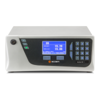
Instrument
A standard Serinus 30 draws ambient air from within its localised area when performing a background
while when sampling it draws the sample form a sample manifold. The difference between air sources
(sample and background) may alter readings on a trace level instrument. Trace instruments can detect
these slight differences so background and sample air must be drawn from an identical source. The
trace instruments obtain background air from the same source as the sample air, helping standardise
air samples and eliminating potential differences such as humidity.
Connect 1/4” virgin PTFE FEP tubing between the sample manifold and the sample inlet on
the instrument.
Connect 1/4” virgin PTFE FEP tubing from the BGnd Air Port to the sample manifold. Or if
no ports are available on the sample manifold add a tee connection with the tubing going
to the sample inlet on the instrument.
8.7.6 Trace Operation
Please refer to Section 9.5 for a detailed pneumatic diagram.
Pneumatics
A standard Serinus 30 instrument uses calibration valves to supply sample, span and zero air to the
inlet. The small error created from delivering gas through different lines is not measurable in standard
instruments but can offset results in a trace level instrument. To eliminate this difference the zero and

 Loading...