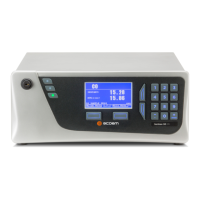
1.5 Instrument Description
The major components of the Serinus 30 are described below:
Figure 3 – Internal Components Diagram
1.5.1 Calibration Valve Manifold
Refer to Figure 3 for the location of calibration valve manifold. The calibration valve manifold switches
between sample, calibration and background gas.
Figure 4 – Calibration Valve Manifold

 Loading...