FloBoss 407 Instruction Manual
Rev 5/00 4-7
DOC0245A
U1
C1
U4
R4
R3
Y1
U2
C4
C6
U5
FB
FB6
C7
CR5
RP1
DSR
CR7
CR6
OH RI
CR4
CR3
CR2
TXDDTR RXD
30
2
1
P1
1
2
30
J1
U3
FB4
FB5
30
2
1
J2
C12
C11
1
2
30
P3
C17
COM PORTS
C13
U7
C14
C16
R5
U6
C8
C9
FB
FB7
C10
FB8
U8
C18
C15
C19
FB3
FB2
R1
R2
FB1
C2
C5
CR1
C3
1
P2
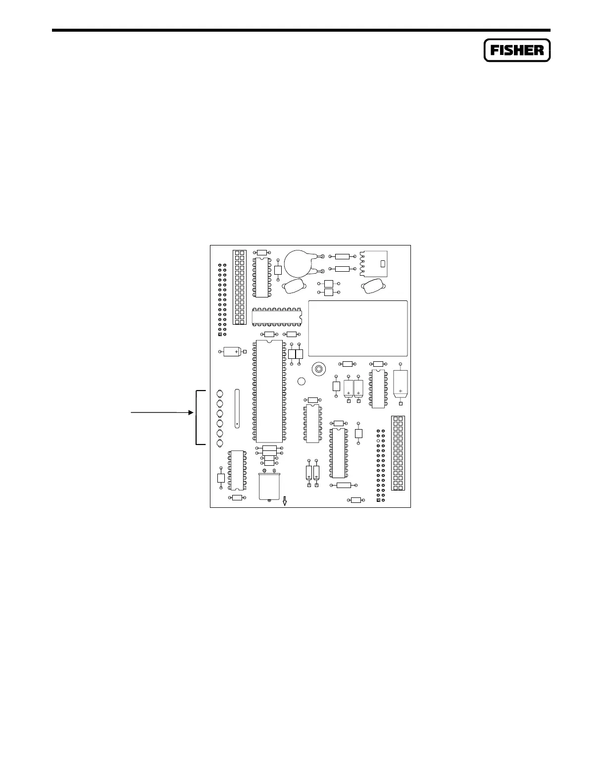
4.2.5 Dial-Up Modem Communications Card
The Dial-up Modem Communications Card supports V.22 bis/2400 baud communications with auto-
answer/auto-dial features. Refer to Figure 4-5. The modem card is FCC part 68 approved for use with
public-switched telephone networks (PSTNs). The FCC label on the card provides the FCC registration
number and the ringer equivalent. The modem card has automatic adaptive and fixed compromise
equalization, thereby eliminating the need for pots to adjust or jumpers to move during installation and
setup.
LED INDICATORS
Figure 4-5. Dial-up Modem Communications Card
The modem card interfaces to two-wire, full-duplex telephone lines using asynchronous operation at
data rates of 600, 1200, or 2400. The card interfaces to a PSTN through an RJ11 jack. The modem can
be controlled using industry-standard AT command software. A 40-character command line is
provided for the AT command set, which is compatible with EIA document TR302.2/88-08006.
LED indicators on the card show the status of the RXD, TXD, DTR, DSR, RI, and OH control lines.
Refer to Table 4-1. The modem card also provides RS-232 level output signals for an analyzer. When
activated as described in Section 4.4.5, these signals are available at the COM2 terminal block.

 Loading...


