FloBoss 407 Instruction Manual
3-30 Rev 5/00
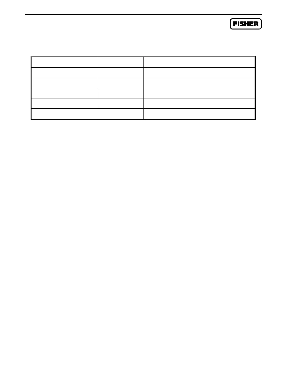
Table 3-2. Analog Input Module Typical Configuration Values
PARAMETER VALUE CORRESPONDS TO:
Adj. A/D 0 % 800 1 volt dc across R
s
(scaling resistor R1)
Adj. A/D 100 % 4000 5 volts dc across R
s
Low Reading EU 0.0000 EU value with 1 volt dc across R
s
High Reading EU 100.0 EU value with 5 volts dc across R
s
Filtered EUs xxxxx Value read by AI module
When the value of Filtered Engineering Units (EU) is -25% of span as configured above, it is an
indication of no current flow (0 mA), which can result from open field wiring or a faulty field device.
When the value of Filtered EUs is in excess of 100% of span as configured above, it is an indication of
maximum current flow, which can result from shorted field wiring or a faulty field device.
When the value of Filtered EUs is between the low and high readings, you can verify the accuracy of
the reading by measuring the voltage across scaling resistor R
s
(V
rs
) with the multimeter. To convert
this reading to the filtered EUs value, perform the following:
Filtered EUs = [((V
rs
- 1)/4) × Span] + Low Reading EU,
where Span = High Reading EU - Low Reading EU
This calculated value should be within one-tenth of one percent of the Filtered EUs value measured by
the ROC/FloBoss. To verify an accuracy of 0.1 percent, read the loop current with a multimeter
connected in series with current loop. Be sure to take into account that input values can change rapidly,
which can cause a greater error between the measured value and the calculated value.
If the calculated value and the measured value are the same, the AI module is operating correctly.
3.5.2 Analog Output Modules
The Analog Output module is a source for current loop or voltage devices. Two test procedures are
provided to verify correct operation. Use the first procedure to check current loop source installations
and the second procedure to check voltage source installations.

 Loading...


