FloBoss 407 Instruction Manual
Rev 5/00 1-3
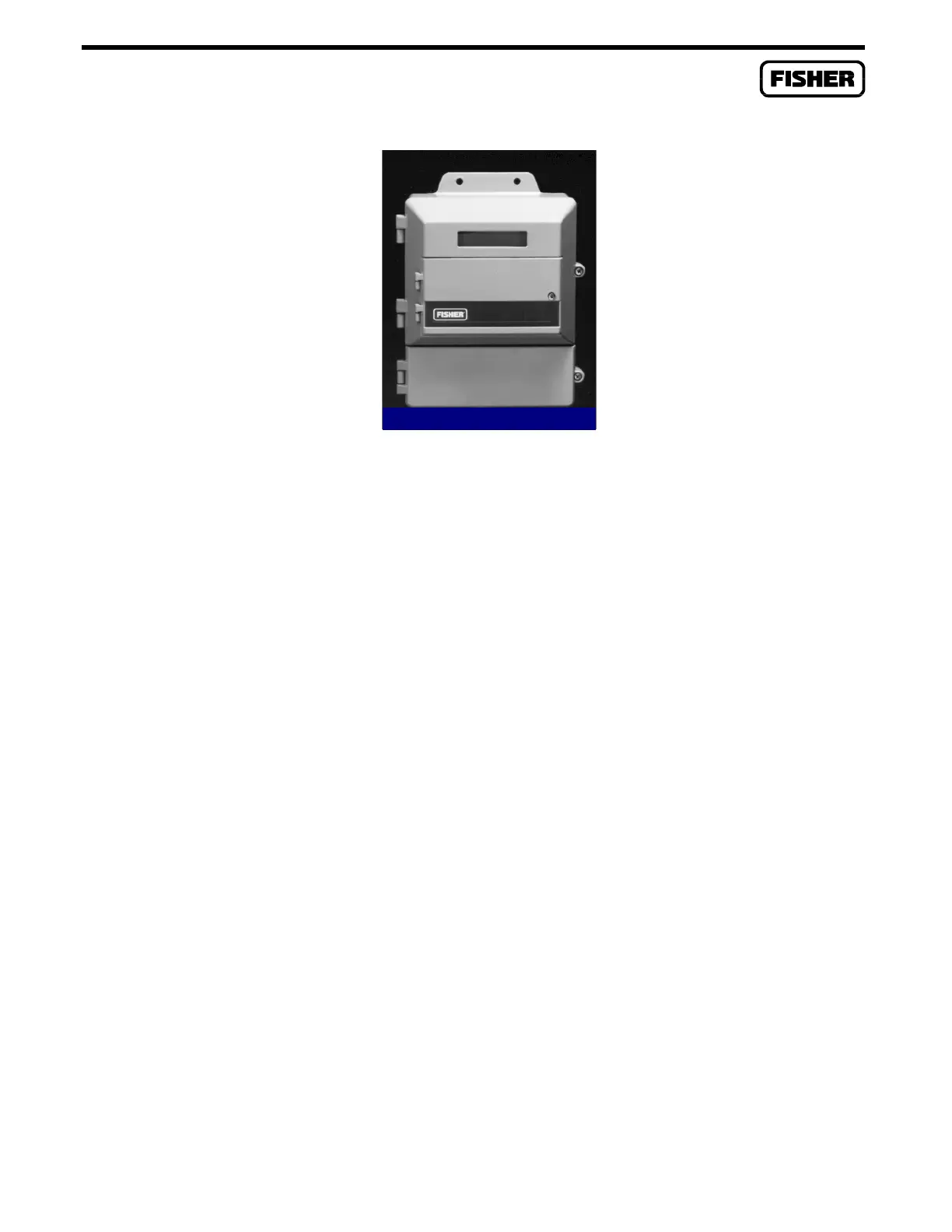
Figure 1-1. FloBoss 407 Flow Manager
Physically, the FloBoss 407 consists of two printed circuit cards, a keypad, and a display housed in a
compact weather-tight case. The printed circuit cards are the processor board and the termination
board.
Built into the termination board are two analog input (AI) channels. Moving a jumper on the
termination board changes one of the built-in analog inputs to a pulse input (PI). The pulse input can be
wired either as a FloBoss-powered or a device-powered, medium-speed pulse counter. The pulse
circuitry is optically coupled to isolate the termination board from the input signal.
In addition, the termination board has slots for four plug-in input/output (I/O) modules (also called
modular I/O). The plug-in I/O modules allow any combination of discrete inputs, discrete outputs,
analog inputs, analog outputs, or pulse inputs an application requires.
NOTE
I/O modules must not be used as flow inputs for Industry Canada approved
FloBoss 407 units.
The built-in Liquid Crystal Display (LCD) and membrane keypad provide the ability to look at data and
configuration parameters while on site. The keypad also permits limited editing of parameter values.
The FloBoss 407 can have up to four Multi-Variable Sensor (MVS) devices connected to it. The MVS
provides the differential pressure, static pressure, and temperature inputs needed for performing orifice
flow calculations. As many as four MVS devices (one of which can be an integral MVS) can be used
with a FloBoss 407. The integral MVS is factory-mounted to the bottom of the enclosure with a
coupler and further secured with a stiffening plate. For detailed information on the MVS, refer to
Appendix B.

 Loading...


