Chapter 5: Installation
104 EST3X Technical Reference Manual
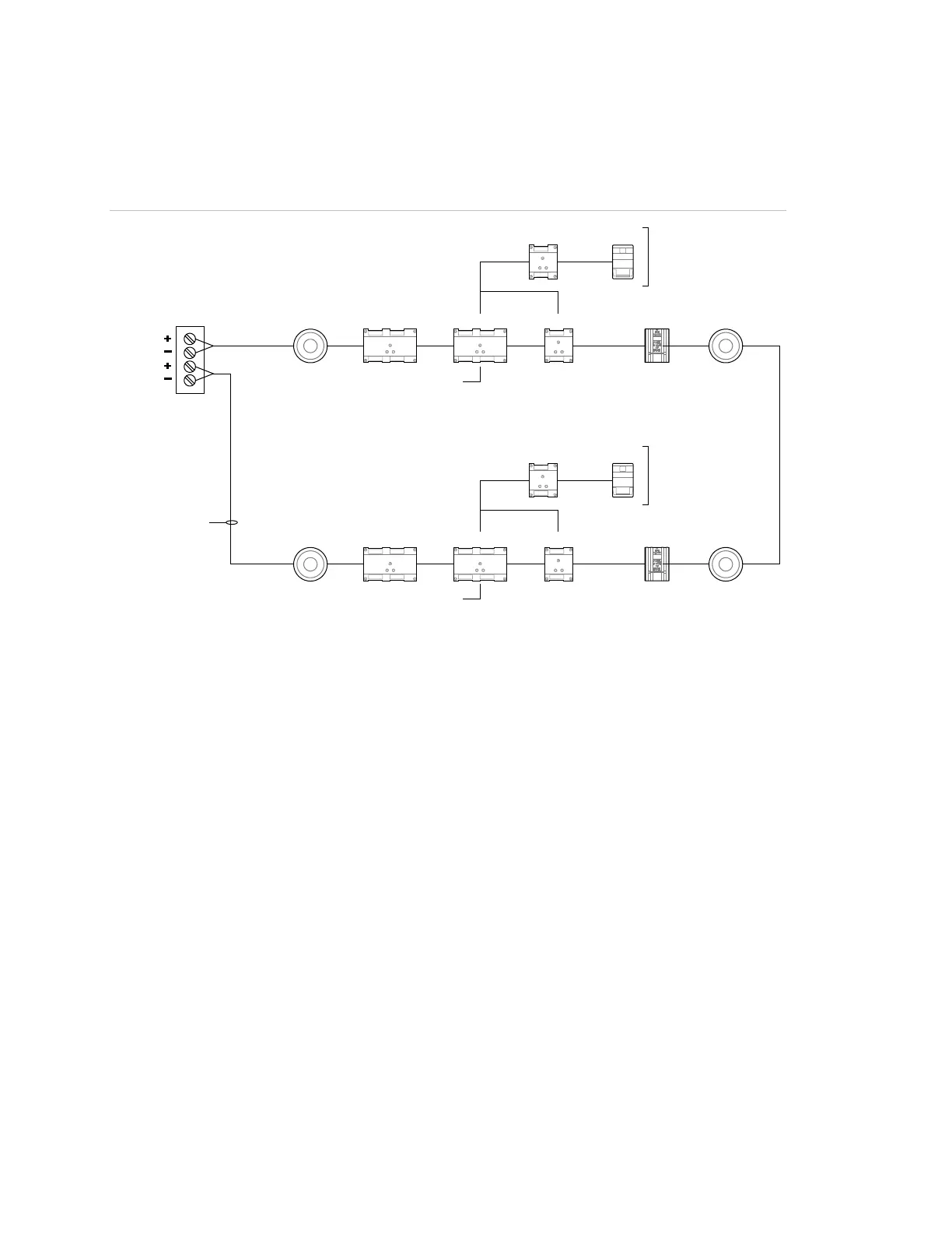
Figure 21 shows a Signature loop wired as Class A for notification circuit
synchronization.
Figure 21: Class A Signature wiring for notification circuit signal synchronization
IM
IM
SIGA_B
SIGA_B
SIGA_A
SIGA_A
IPHS
IPHS
270
270
CC1
CC1
CR
CR
IPHS
IPHS
(1) (2)
(3)
(6)
(4)
(4)
(5)
(5)
(1) (2)
(7)
2) Temporal horn/strobe
3) Notification zone 1
(6) Notification zone 2
(7) Class A (required)
Figure 22 on page 105 shows two NACs on a Signature data loop. Each NAC is
controlled by a SIGA-CC1S module, one for audible appliances and one for
visible appliances. The SIGA-CC1S modules provide signal synchronization for
both NACs.
As in Figure 20, this configuration allows the audible appliances to be silenced
independently of the visible appliances. This operation is optional and may or
may not be required for your project.