Do you have a question about the Estun Summa Series and is the answer not in the manual?
Explains the manual's objective and the information it provides about the servodrive.
Defines key terms used throughout the manual for clarity and understanding.
Provides essential safety guidelines for handling and operating the servodrive.
Outlines critical guidelines for storing the product to maintain its condition and safety.
Details necessary precautions to ensure safe and correct installation of the servodrive.
Provides critical safety guidelines related to the electrical wiring of the servodrive.
Lists important safety measures to follow during the operation of the servodrive.
Outlines safety measures and procedures for maintaining the servodrive.
Provides guidelines for the safe and compliant disposal of the product.
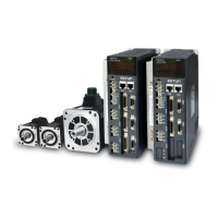
Highlights the key characteristics and advantages of the Summa Series AC Servo Drive.
Explains how to read and understand the information presented on the drive's nameplate.
Details the naming convention and structure used for designating different product models.
Identifies and describes the different physical components and connectors of the servodrive.
Lists the electrical ratings, performance specifications, and environmental conditions for the drive.
Provides the physical dimensions and mounting hole details of the servodrive.
Illustrates the typical system setup and the connection of peripheral devices with the servodrive.
Outlines essential safety and operational guidelines for installing the servodrive.
Describes the recommended mounting methods and orientation for the servodrive installation.
Provides specific dimensions for the mounting holes required for servodrive installation.
Specifies the required clearances for mounting drives within a control cabinet for proper ventilation.
Details the installation conditions necessary to meet EMC certification testing requirements.
Explains the EMC installation conditions used for testing and compliance.
Describes the proper method for mounting ferrite coils to reduce electromagnetic interference.
Lists essential safety precautions and guidelines to follow before and during wiring.
Provides fundamental safety measures applicable to all wiring tasks involving the servodrive.
Details methods and precautions to minimize noise interference in the wiring and system.
Explains the critical grounding measures required for safety and proper operation.
Provides fundamental circuit diagrams illustrating common wiring configurations for the servodrive.
Details the procedures and considerations for connecting the power supply to the servodrive.
Shows the layout and specifications of the power supply terminals on the servodrive.
Provides a step-by-step guide for the wiring process of the main and control circuit terminals.
Presents schematic diagrams for various power supply input configurations (three-phase, single-phase, DC).
Explains how to correctly wire the motor to the servodrive, including brake and non-brake terminals.
Details the wiring procedure for connecting the motor encoder and external encoder to the servodrive.
Describes how to connect digital and analog I/O signals to the servodrive's connector.
Explains how to establish communication links, including EtherCAT and USB.
Details the specifications and connection methods for EtherCAT communication cables.
Explains how to connect the servodrive to a PC using a USB cable for software operation.
Provides instructions for wiring an external encoder for fully-closed loop control systems.
Introduces the servodrive's front panel operator, its keys, and basic functions.
Describes the function of each key on the servodrive's panel operator.
Explains how to navigate and select different operating modes using the panel operator.
Describes how to interpret the information displayed on the panel operator in the status mode.
Details how to access and adjust the servodrive's parameters via the panel operator.
Introduces the ESView V4 software for servodrive configuration and monitoring.
Guides the user through the installation process of the ESView V4 software on a PC.
Explains how to launch and connect to the servodrive using the ESView V4 software.
Describes how to upload, modify, download, and manage parameters using the ESView V4 software.
Explains how to use the monitoring functions of ESView V4 to observe drive status and signals.
Provides an overview of EtherCAT technology and its application in motion control.
Explains the EtherCAT protocol, its real-time capabilities, and network topology.
Lists the technical specifications for EtherCAT communication, including standards, connectors, and cable types.
Identifies key parameters that need to be checked for successful EtherCAT network communication.
Explains fundamental concepts of EtherCAT, including the CANopen over EtherCAT reference model.
Illustrates the architecture of the CANopen over EtherCAT communication protocol.
Describes how to use EtherCAT slave information files (XML format) for master configuration.
Explains the different communication states and transitions within the EtherCAT protocol.
Describes how process data is mapped and transferred using PDOs in EtherCAT communication.
Explains the use of SDOs for asynchronous data transfer, such as parameter configuration.
Details the structure and content of emergency messages used for alarm reporting in EtherCAT.
Explains the mechanism of distributed clock synchronization in EtherCAT for precise timing.
Describes how indicator lamps on the panel operator and RJ45 connectors show communication status.
Explains the meaning of the SYS, RUN, and ERR indicator lamps on the panel operator.
Explains the function of the Link/Activity indicators on the RJ45 connectors for communication status.
Explains how to set the gear ratio for converting between motor and driving shaft units.
Describes the device control mechanisms and the CiA402 state machine.
Details the various states and transitions within the CiA402 drive state machine.
Explains the five supported stop modes for the servodrive, including Quick Stop and Shutdown.
Lists and describes the eight supported control modes for the servodrive.
Explains how to select and view the current operation mode of the servodrive.
Provides notes and considerations for changing the control mode of the servodrive.
Specifies the supported communication cycle times for various control modes.
Explains the principles and operation of position control modes.
Details the operation of the Profile Position mode, including trajectory generation and control.
Describes the Interpolated Position mode for controlling multiple axes or single axis with time interpolation.
Explains the Cyclic Synchronous Position mode and its reliance on cyclic synchronization.
Explains the homing procedure for establishing the motor's home position and relationship to zero.
Details the Homing mode, including its purpose and how it establishes the home position.
Describes various homing methods based on limit switches and index pulses.
Explains the principles of velocity control for the servodrive.
Details the Profile Velocity mode, where the host controller provides target speed and acceleration.
Describes the Cyclic Synchronous Velocity mode, using cyclic synchronization for target speed.
Explains the principles of torque control for the servodrive.
Details the Profile Torque mode where the host controller provides target torque and slope.
Describes the Cyclic Synchronous Torque mode, using cyclic synchronization for target torque.
Explains how to set limits on the motor's output torque.
Describes how to connect digital and analog I/O signals to the servodrive's connector.
Explains how to allocate input signals to specific pins on the I/O connector.
Details how to allocate output signals to specific pins on the I/O connector.
Explains the different methods for limiting the motor's output torque.
Describes how to limit torque using internal parameters.
Explains how to limit torque using external input signals.
Describes how to limit torque using the /CLT output signal.
Explains the soft start function for smooth acceleration and deceleration.
Describes the SEMI F47 function for handling momentary power interruptions and voltage drops.
Details the necessary steps and checks before performing trial operation.
Lists crucial inspections and confirmations required for safe and correct trial operation.
Explains how to perform trial operation of the motor without any load connected.
Lists the essential preparations required before executing motor jogging.
Lists the recommended tools for performing motor jogging and trial operations.
Provides detailed instructions for performing JOG operation using the panel operator.
Explains how to perform JOG operation using the ESView V4 software.
Details the procedures and precautions for operating the motor with a load attached.
Lists important warnings and precautions to observe before operating the motor with a load.
Outlines the necessary preparations before performing the trial operation procedure for the machine and motor.
Provides a step-by-step guide for the trial operation of the machine and motor.
Explains how to perform continuous operation using preset patterns for travel, speed, and movements.
Lists the essential checks before executing program jogging operations.
Describes the two operation patterns (PJOG0, PJOG1) used in program jogging.
Lists the parameters that need to be set for program jogging operations.
Lists the tools recommended for performing program jogging operations.
Provides step-by-step instructions for performing program jogging using the panel operator and ESView V4.
Provides a general introduction to the servo tuning process and its importance.
Explains the fundamental principles of servo tuning and performance evaluation.
Illustrates the servo control block diagram, showing the interaction of position, speed, and torque loops.
Outlines the iterative process and methods for tuning the servodrive performance.
Lists critical safety precautions and checks to perform before starting the tuning process.
Introduces the different tuning modes available for optimizing servo performance.
Explains the tuning-less function which performs auto-tuning automatically when the servo is turned on.
Details the one-parameter auto-tuning process for adjusting servo parameters based on operating state.
Describes the process of manually adjusting gain parameters to achieve desired servo performance.
Introduces the Auto-Tuning Tool and Manual Tuning Tool for optimizing servo performance.
Explains how to use the Auto-Tuning Tool for automatic servo tuning and parameter adjustment.
Guides the user on using the Manual-Tuning Tool to adjust servo gain parameters based on waveform data.
Explains how to select the speed feedback source (encoder or observed speed).
Covers advanced adjustment functions for optimizing servo system performance.
Explains the gain switching function for using different gain parameters at different stages of operation.
Describes how to switch between P and PI control for the speed loop based on conditions.
Explains the use of speed and torque feedforward to improve servo response.
Details how to compensate for load friction to improve servo system stability.
Explains how to improve anti-load disturbance performance by compensating for load torque.
Describes the Model Following Control for improving response and positioning performance.
Covers techniques for suppressing mechanical vibration in the servo system.
Explains the use of notch filters to eliminate vibration caused by mechanical resonance.
Describes the IF vibration suppression filter for processing speed deviation and torque compensation.
Explains how to suppress low-frequency jitter during position control using Model Following Control.
Details the automatic vibration suppression function that identifies and suppresses vibration automatically.
Introduces tools for diagnosing system performance and identifying issues.
Explains how to calculate the load inertia percentage for tuning purposes.
Describes how to measure mechanical frequency characteristics of the system using the drive and PC.
Explains how to use the FFT function to analyze vibration frequencies of the machine.
Details how to perform friction analysis to set parameters for friction compensation.
Introduces the concept of fully-closed loop systems and their benefits for high-precision positioning.
Provides the steps for commissioning the drive for correct operation in a fully-closed loop configuration.
Lists the parameters that need to be set for proper fully-closed loop control operation.
Illustrates the control block diagram for fully-closed loop operation.
Explains how to set the motor direction and machine movement direction for closed-loop control.
Details how to enable and configure the external encoder for fully-closed loop control.
Explains how to configure the divided pulse output settings for an external encoder.
Describes how to set up alarms for detecting deviations between motor and external encoder positions.
Introduces the Safe Torque Off (STO) function and its safety compliance.
Lists the environmental operating conditions for the servodrive.
Shows the terminal layout for the STO safety function connection.
Explains the operational principles and features of the STO safety function.
Describes the EDM signal used for monitoring failures in the STO function.
Explains the safe state behavior of the drive when the STO function is activated.
Explains the S-RDY signal's behavior in different states, including Safe State.
Describes the /BK signal's behavior when the STO function is active.
Details the stopping methods applied when the STO function takes effect.
Explains how the deviation counter is reset when the STO function or other conditions are met.
Provides instructions on connecting and disconnecting a safety function device.
Explains the implications and procedure for disconnecting a safety function device.
Details the process of connecting a safety function device to the STO terminals.
Provides comprehensive lists and details of all available parameters for configuration.
Explains how to read and understand the format and content of the parameter lists.
Provides detailed descriptions, ranges, and default values for each parameter.
Lists and explains the different alarm classifications and panel displays.
Describes the object dictionary that defines the servodrive's data and communication objects.
Lists general objects like Device Type and Error Register with their data descriptions.
Explains how to map objects to PDOs for real-time data transfer in EtherCAT.
Presents parameters used in specific modes like SinglePos and MultiPos.
Details objects related to device control, such as Error Code and Controlword.
Lists objects and parameters specific to the Profile Position mode.
Lists objects and parameters related to the homing function.
Lists objects that define position demand, actual position, and error values.
Lists objects related to the Interpolated Position Mode and its submodes.
Explains the Cyclic Synchronous Position mode and its reliance on cyclic synchronization.
Lists objects for Profile Velocity and Cyclic Synchronous Velocity modes, including speed and window settings.
Lists objects relevant to Profile Torque and Cyclic Synchronous Torque modes.
Lists objects related to setting maximum, positive, and negative torque limits.
Lists objects for digital input and output signal allocations.
Provides a comprehensive list of all objects in the dictionary with their index, name, and type.
| Brand | Estun |
|---|---|
| Model | Summa Series |
| Category | Servo Drives |
| Language | English |