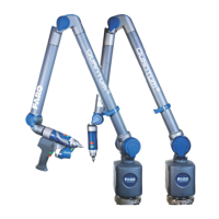
FaroArm® Quantum
August 2017
111
Chapter 4: Probes
Probe Modules for the TP-20 Probe
Probe modules are available from Renishaw in three trigger force ratings:
• Standard Force Probe Module (Black cap)
• Medium Force Probe Module (Gray cap)
• Extended Force Probe Module (Brown cap)
Refer to the Renishaw TP-20 Installation and User’s Manual for the TP-20 Probe
assembly instructions.
Measuring Software
The measuring software must be configured for the probe. If you are using
CAM2 Measure:
1. Open the DEVICE CONTROL panel and click PROBE MANAGEMENT. See
“Probes” on page 55.
2. If the TP-20 probe adapter is not automatically recognized, click Find.
Ensure the Auxiliary port is active and the De-bounce Time is not zero
(0).
See “Edit Probe” on page 57.
3. Compensate the probe using the FARO Compensation Sphere, or any
precision sphere, after installation. For more information, see
“Sphere
Compensation Method - 6-Axis” on page 67 or “Sphere Compensation
Method - 7-Axis” on page 70.
NOTE: The probe compensation information stores for the adapter.
However, since the probe tip is removable, do not rely on an existing
compensation unless you are certain that the TP-20 body or the probe tip
have not been changed.
Some software packages have other probe options that must also be controlled.
See the Renishaw User’s Manual for more information.
Operation
The probe digitizes a point when it makes contact with an object. The Handle
LED changes to red and back to green after the De-bounce Time. Additional
points will not record until after the de-bounce time has elapsed.
NOTE: The green and red handle buttons are active. Hold the handle in a
manner so that you do not accidentally press the green or red buttons while
measuring.
08m80e00_FaroArm_Quantum.book Page 111 Tuesday, August 22, 2017 11:03 AM

 Loading...