FaroArm® Quantum
August 2017
104
Chapter 4: Probes
DRO
Some software packages add a Digital ReadOut (DRO) window to the screen.
The DRO window displays the current location of the probe in the current
coordinate system.
• If the FARO Laser Line Probe is in range, the X, Y, Z coordinate is the center
of the laser line. Note that this may not be the center of the complete laser
line because some part of the laser line may be out of range.
• If the FARO Laser Line Probe is out of range, then no coordinate is available
and the DRO displays a row of asterisks (******).
FARO Laser Line Probe Settings
Modify the settings of the FARO Laser Line Probe for your part. The default
settings are for digitizing the compensation sphere or plane that has an opaque
white surface. You can control the following:
• Scan Rate - the number of lines per second that the FARO Laser Line Probe
records and sends to your current file. Fewer lines per second requires you to
move the FARO Laser Line Probe slower.
• Scan Density - the amount of points each line contains. More points in each
line creates a larger file. If you are digitizing a relatively flat surface, use less
points.
• Material - controls the camera which records the laser line. Different part
material colors and textures reflect the laser line differently.
• Advanced Settings - controls the exposure settings of the camera.
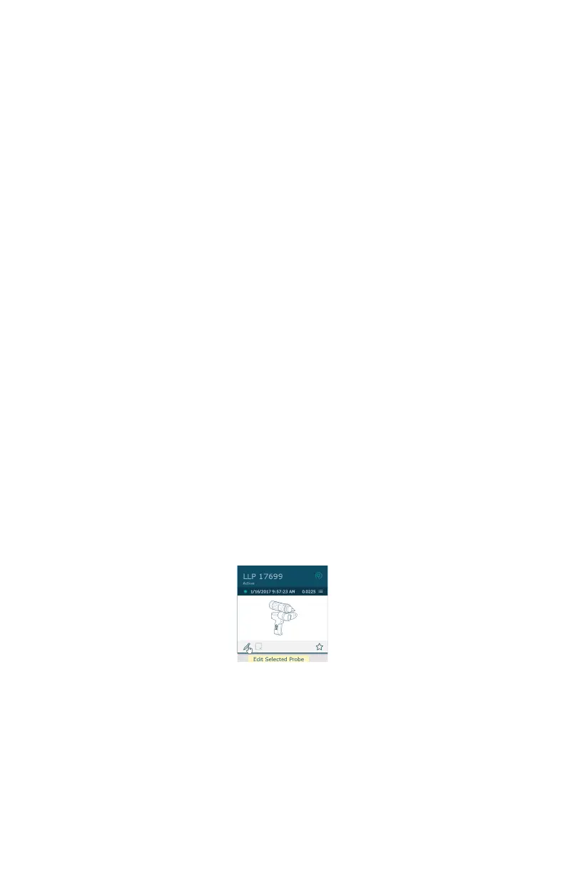
To change the FARO Laser Line Probe settings:
• Choose the Laser Probe probe in the PROBES dialog box.
•Click Edit.
Figure 4-18 Probes dialog box
08m80e00_FaroArm_Quantum.book Page 104 Tuesday, August 22, 2017 11:03 AM