FaroArm® Quantum
August 2017
3
Chapter 1: Introduction
General Information
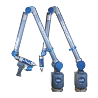
The Quantum is a multiple-axis, articulated arm with a spherical working
volume. Each joint has a rotary optical encoder. The signals from these encoders
are processed, using advanced error coding and temperature compensation
technology, and positional data is sent to the host computer using various wired
and wireless communication protocols.
The Base Assembly contains the majority of the electronics, including a power
on/off button, wireless on/off buttons, status indicators, battery pack bay, and
communication ports. There are five major communications ports on the
Quantum located on the Base Assembly:
• USB 2.0 Host Port
• USB 2.0 Device
• Ethernet (802.3)
• Bluetooth (Internal Base Module)
• Wireless Local Area Network (WLAN 802.11 - Internal Base Module)
The Quantum uses a non-volatile read/write FLASH memory. This memory
stores programming and some compensation data for the Quantum. There are
proprietary methods that are capable of erasing, reading, and writing the FLASH
memory. These methods are used during manufacturing and field updating.
Security for the FLASH is limited to the anonymity of the access methods and
the unavailability of documentation for the address structure of the FLASH
memory.
The only dynamic data stored in the Quantum are settings which relate directly to
the operation of the Quantum. Examples include the probe XYZ position,
connection settings, etc. The Quantum does not maintain in memory, or cache,
measurement data of any type. Measurements recorded with the Quantum are
sent directly to the properly connected computer.
The Probe End Assembly is found at the farthest point from the base. It is free to
rotate, has two control (red and green) buttons and two circular LED indicators
that provide visual feedback to the user. This assembly provides for the
attachment of probes and handle accessories.
08m80e00_FaroArm_Quantum.book Page 3 Tuesday, August 22, 2017 11:03 AM