The two left phases are considered as normal, whereas the right phase shows a very
clear excess temperature. Actually, the operating temperature of the left phase is
+68°C (+154°F), that is, quite a substantial temperature, whereas the faulty phase
to the right shows a temperature of +86°C (+187°F). This means an excess temper-
ature of +18°C (+33°F), that is, a fault that has to be attended to quickly.
For practical reasons, the (normal, expected) operating temperature of a component
is taken as the temperature of the components in at least two out of three phases,
provided that you consider them to be working normally.. The ‘most normal’ case is
of course that all three phases have the same or at least almost the same temperature.
The operating temperature of outdoor components in substations or power lines is
usually only 1°C or 2°C above the air temperature (1.8°F or 3.6°F). In indoor substa-
tions, the operating temperatures vary a lot more.
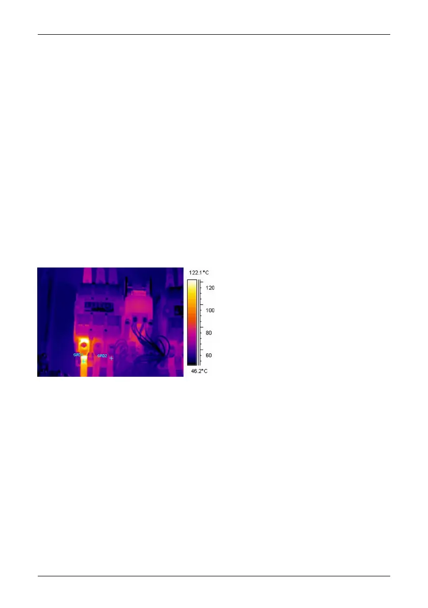
This fact is clearly shown by the image below as well. Here the left phase is the one,
which shows an excess temperature. The operating temperature, taken from the two
‘cold’ phases, is +66°C (+151°F). The faulty phase shows a temperature of +127°C
(+261°F), which has to be attended to without delay.
10713503;a5
Figure 28.9 An infrared image of indoor electrical equipment (2).
28.3.5 Classification of faults
Once a faulty connection is detected, corrective measures may be necessary—or
may not be necessary for the time being. In order to recommend the most appropriate
action the following criteria should be evaluated:
■ Load during the measurement
■ Even or varying load
■ Position of the faulty part in the electrical installation
■ Expected future load situation
■ Is the excess temperature measured directly on the faulty spot or indirectly through
conducted heat caused by some fault inside the apparatus?
Publ. No. 1558792 Rev. a460 – ENGLISH (EN) – July 1, 2010 187
28 – Introduction to thermographic inspections of electrical installations

 Loading...