5-24
F codes
E codes
C codes
P codes
H codes
A codes
b codes
r codes
J codes
d codes
U codes
y codes
Chap. 5 FUNCTION CODES
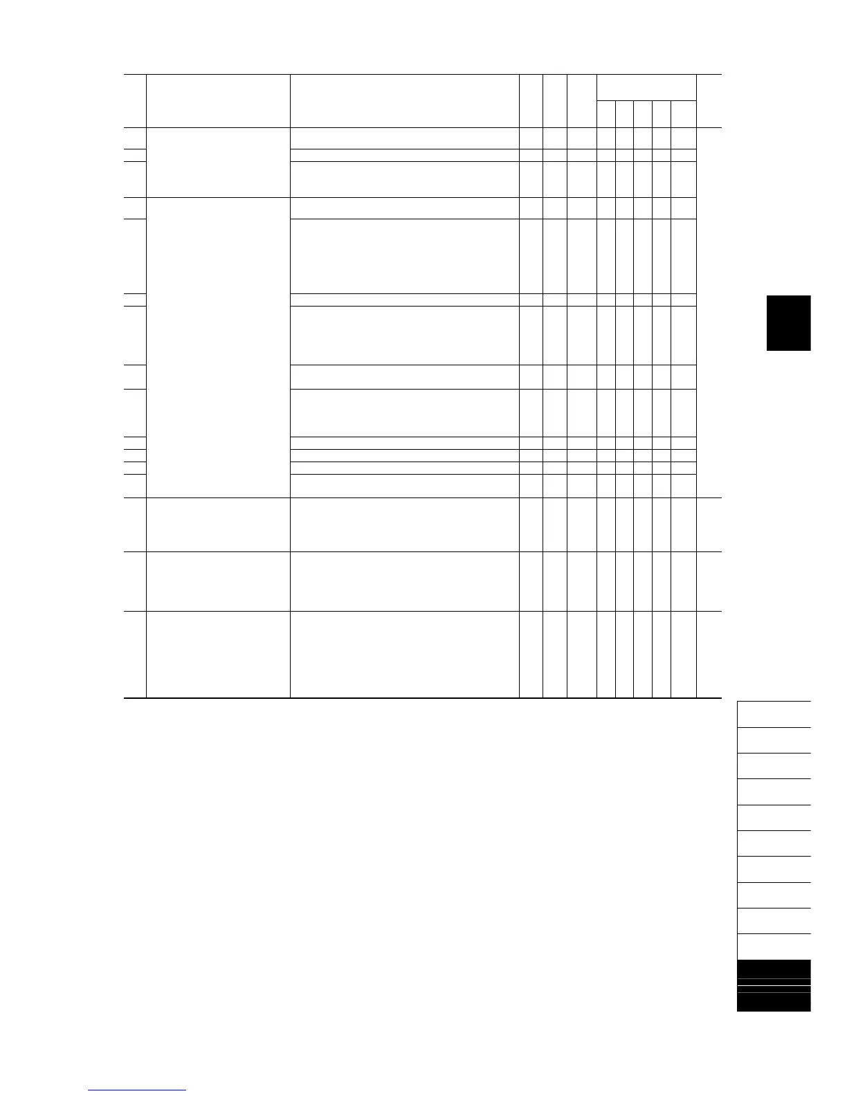
Drive control
Code Name Data setting range
Change when
running
Data copying
Default
setting
V/f
PG
V/f
w/o
PG
w/
PG
Torque
control
Refer
to
page:
y08 RS-485 Communication 1
(No-response error detection time)
0: No detection; 1 to 60 s Y Y 0 Y Y Y Y Y 5-147
y09 (Response interval) 0.00 to 1.00 s Y Y 0.01 Y Y Y Y Y
y10 (Protocol selection) 0: Modbus RTU protocol
1: FRENIC Loader protocol (SX protocol)
2: Fuji general-purpose inverter protocol
Y Y 1 Y Y Y Y Y
y11 RS-485 Communication 2
(Station address)
1 to 255 N Y 1 Y Y Y Y Y
y12 (Communications error processing) 0: Immediately trip with alarm
erp
1: Trip with alarm
erp
after running for the period specified
by timer y13
2: Retry during the period specified by timer y13. If the retry
fails, trip with alarm
erp
. If it succeeds, continue to
run.
3: Continue to run
Y Y 0 Y Y Y Y Y
y13 (Timer) 0.0 to 60.0 s Y Y 2.0 Y Y Y Y Y
y14 (Baud rate) 0: 2400 bps
1: 4800 bps
2: 9600 bps
3: 19200 bps
4: 38400 bps
Y Y 3 Y Y Y Y Y
y15 (Data length) 0: 8 bits
1: 7 bits
Y Y 0 Y Y Y Y Y
y16 (Parity check) 0: None (2 stop bits)
1: Even parity (1 stop bit)
2: Odd parity (1 stop bit)
3: None (1 stop bit)
Y Y 0 Y Y Y Y Y
y17 (Stop bits) 0: 2 bits 1: 1 bit Y Y 0 Y Y Y Y Y
y18 (No-response error detection time) 0: No detection; 1 to 60 s Y Y 0 Y Y Y Y Y
y19 (Response interval) 0.00 to 1.00 s Y Y 0.01 Y Y Y Y Y
y20 (Protocol selection) 0: Modbus RTU protocol
2: Fuji general-purpose inverter protocol
Y Y 0 Y Y Y Y Y
y97 Communication Data Storage
Selection
0: Save into nonvolatile storage (Rewritable times limited)
1: Write into temporary storage (Rewritable times unlimited)
2: Save all data from temporary storage to nonvolatile one
(After saving data, the y97 data automatically returns to
"1.")
Y Y 0 Y Y Y Y Y 5-149
y98 Bus Link Function (Mode selection) Frequency command Run command
0: Follow H30 data Follow H30 data
1: Via fieldbus option Follow H30 data
2: Follow H30 data Via fieldbus option
3: Via fieldbus option Via fieldbus option
Y Y 0 Y Y Y Y Y 5-105
5-149
y99 Loader Link Function
(Mode selection)
Frequency command Run command
0: Follow H30 and y98 data Follow H30 and y98 data
1: Via RS-485 link Follow H30 and y98 data
(FRENIC Loader)
2: Follow H30 and y98 data Via RS-485 link
(FRENIC Loader)
3: Via RS-485 link Via RS-485 link
(FRENIC Loader) (FRENIC Loader)
Y N 0 Y Y Y Y Y 5-149

 Loading...


