5-35
The pulse train sign, forward/reverse rotation pulse, and A/B phase difference define the polarity of the pulse train input.
Combination of the polarity of the pulse train input and the FWD/REV command determines the rotational direction of
the motor. The table below shows the relationship between the polarity of the pulse train input and the motor rotational
direction.
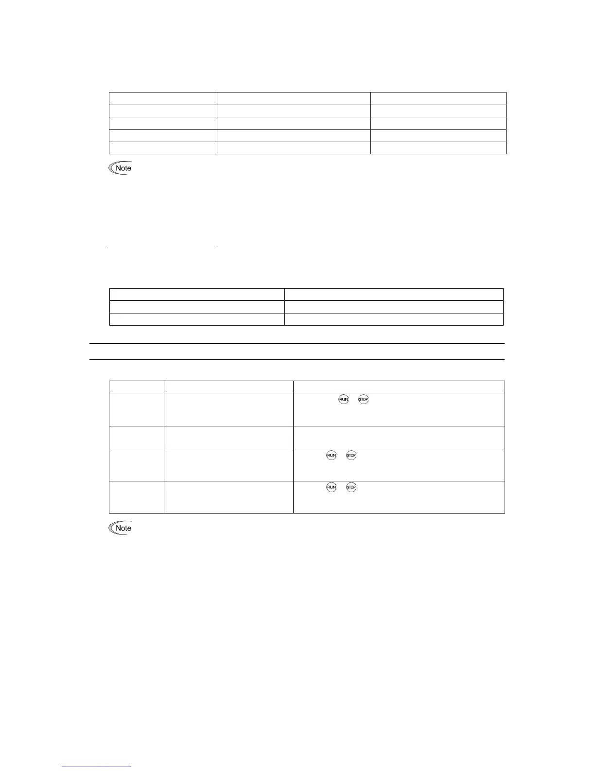
Pulse Train Polarity Run command Motor rotational direction
Positive (+) FWD (Run forward command) Forward
Positive (+) REV (Run reverse command) Reverse
Negative (-) FWD (Run forward command) Reverse
Negative (-) REV (Run reverse command) Forward
Mounting an optional PG interface card automatically switches the pulse train input source to the card and
disables the input from the terminal [X7].
Filter time constant (d61)
d61 specifies a filter time constant for pulse train input. Choose an appropriate value for the time constant taking into
account the response speed of the mechanical system since a large time constant slows down the response. When the
reference frequency fluctuates due to small number of pulses, specify a larger time constant.
Switching frequency command
Using the terminal command Hz2/Hz1 assigned to one of the digital input terminals switches between frequency
command 1 (F01) and frequency command 2 (C30).
For details about Hz2/Hz1, refer to E01 to E07 (data = 11).
Terminal command Hz2/Hz1 Frequency command source
OFF Follow F01 (Frequency command 1)
ON Follow C30 (Frequency command 2)
F02 Operation Method
F02 selects the source that specifies a run command.
Data for F02 Run Command Description
0
Keypad
(Rotational direction specified by
terminal command)
Enables the
/ keys to run and stop the motor.
The rotational direction of the motor is specified by terminal
command FWD or REV.
1
External signals
(Digital input terminal commands)
Enables terminal command FWD or REV to run the motor.
2
Keypad
(Forward rotation)
Enables
/ keys to run and stop the motor. Note that
this run command enables only the forward rotation.
There is no need to specify the rotational direction.
3
Keypad
(Reverse rotation)
Enables
/ keys to run and stop the motor. Note that
this run command enables only the reverse rotation.
There is no need to specify the rotational direction.
• When function code F02 = 0 or 1, the "Run forward" FWD and "Run reverse" REV terminal commands must
be assigned to terminals [FWD] and [REV], respectively.
• When the FWD or REV is ON, the F02 data cannot be changed.
• When changing terminal command assignments to terminals [FWD] and [REV] from commands other than
the FWD and REV to the FWD or REV with F02 being set to "1," be sure to turn the target terminal OFF
beforehand; otherwise, the motor may unintentionally rotate.
3-wire operation with external input signals (digital input terminal commands)
The default setting of the FWD and REV are 2-wire. Assigning the terminal command HLD self-holds the forward
FWD or reverse REV run command, to enable 3-wire inverter operation. Short-circuiting the HLD-assigned terminal
and [CM] (i.e., when HLD is ON) self-holds the first FWD or REV at its rising edge. Turning the HLD OFF releases
the self-holding. When no HLD is assigned, 2-wire operation involving only FWD and REV takes effect.
For details about HLD, refer to E01 to E07 (data = 6).