2-1
Chapter 2 MOUNTING AND WIRING THE INVERTER
2.1 Operating Environment
Install the inverter in an environment that satisfies the requirements listed in Table 2.1.
Table 2.1 Environmental Requirements
Item Specifications
Site location Indoors
Surrounding/ambient
temperature
-10 to +50°C (Note 1)
Relative humidity 5 to 95% (No condensation)
Atmosphere
The inverter must not be exposed to dust, direct sunlight, corrosive
gases, flammable gases, oil mist, vapor or water drops.
Pollution degree 2 (IEC60664-1) (Note 2)
The atmosphere can contain a small amount of salt.
(0.01 mg/cm
2
or less per year)
The inverter must not be subjected to sudden changes in
temperature that will cause condensation to form.
Altitude 1,000 m max. (Note 3)
Atmospheric pressure 86 to 106 kPa
55 kW or below (200 V class series)
75 kW or below (400 V class series)
75 kW or above (200 V class series)
90 kW or above (400 V class series)
3 mm (Max. amplitude) 3 mm (Max. amplitude)
2 to less than 9 Hz 2 to less than 9 Hz
9.8 m/s
2
9 to less than 20 Hz 2 m/s
2
9 to less than 55 Hz
2 m/s
2
20 to less than 55 Hz 1 m/s
2
55 to less than 200 Hz
Vibration
1 m/s
2
55 to less than 200 Hz
2.2 Installing the Inverter
(1) Mounting base
Install the inverter on a base made of metal or other non-flammable material. Do not
mount the inverter upside down or horizontally.
Install the inverter on a base made of metal or other non-flammable material.
Otherwise, a fire could occur.
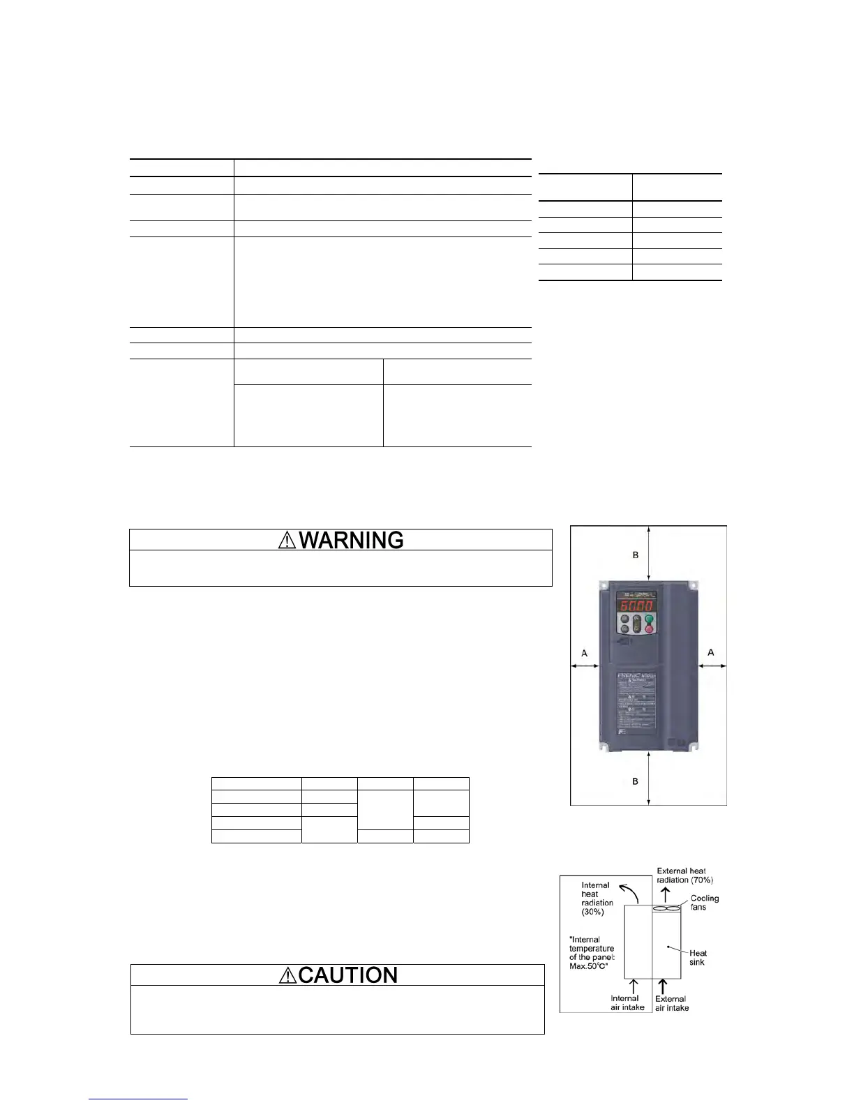
(2) Clearances
Ensure that the minimum clearances indicated in Figure 2.1 and Table 2.3 are maintaine
ventilation inside the panel as the surrounding temperature easily rises. Do not install the
inverter in a small panel with poor ventilation.
When mounting two or more inverters
When mounting two or more inverters in the same unit or panel, basically lay them out
side by side. When mounting them necessarily one above the other, be sure to separate
them with a partition plate or the like so that any heat radiating from an inverter will not
affect the one/s above.
As long as the surrounding temperature is 40°C or lower, inverters with a capacity of 22
kW or below can be mounted side by side without any clearance between them.
Table 2.3 Clearances
(mm)
Inverter capacity A B C
0.4 to 1.5 kW 50
2.2 to 22 kW 10
0
30 to 220 kW
100
100
280 to 630 kW
50
150 150
C: Space required in front of the inverter unit
When employing external cooling
In external cooling, the heat sink, which dissipates about 70% of the total heat (total
loss) generated into air, is situated outside the equipment or the panel. The external
cooling, therefore, significantly reduces heat radiating inside the equipment or panel.
To employ external cooling for inverters with a capacity of 22 kW or below, use the
external cooling attachment option; for those with a capacity of 30 kW or above,
simply change the positions of the mounting bases.
Prevent lint, paper fibers, sawdust, dust, metallic chips, or other foreign materials
from getting into the inverter or from accumulating on the heat sink.
Otherwise, a fire or accident could occur.
Figure 2.2 External Cooling
Table 2.2 Output Current Derating
Factor in Relation to Altitude
Altitude
Output current
derating factor
1000 m or lower 1.00
1000 to 1500 m 0.97
1500 to 2000 m 0.95
2000 to 2500 m 0.91
2500 to 3000 m 0.88
(Note 1) When inverters are mounted
side-by-side without any clearance between
them (22 kW or below), the surrounding
temperature should be within the range from
-10 to +40°C.
(Note 2) Do not install the inverter in an
environment where it may be exposed to lint,
cotton waste or moist dust or dirt which will
clog the heat sink of the inverter. If the
inverter is to be used in such an environment,
install it in a dustproof panel of your system.
(Note 3) If you use the inverter in an altitude
above 1000 m, you should apply an output
current derating factor as listed in Table 2.2.
Figure 2.1 Mounting Direction and
Required Clearances