5-18
Chap. 5 FUNCTION CODES
F codes
E codes
C codes
P codes
H codes
A codes
b codes
r codes
J codes
d codes
U codes
y codes
Drive control
Code Name Data setting range
Change when
running
Data copying
Default
setting
V/f
PG
V/f
w/o
PG
w/
PG
Torque
control
Refer
to
page:
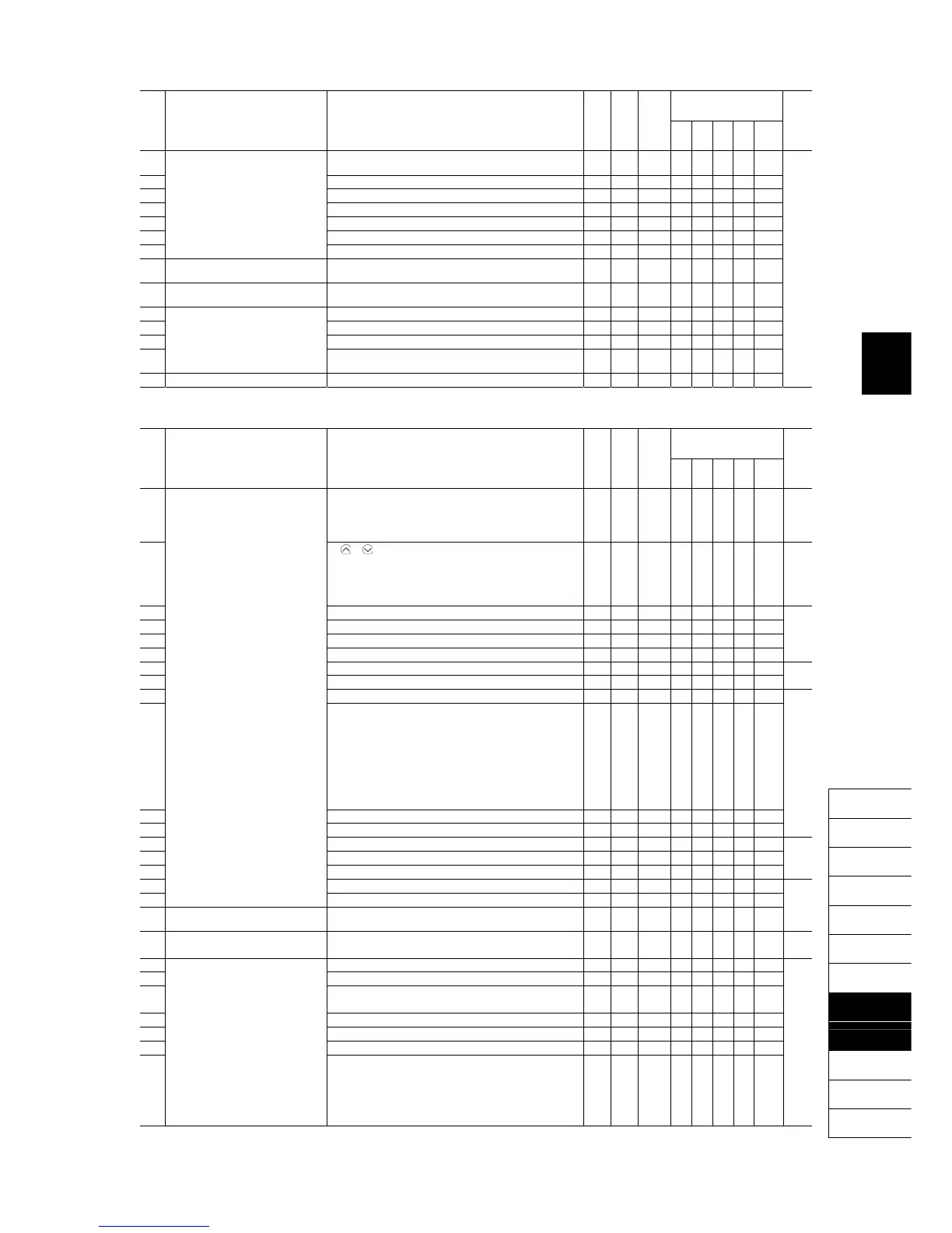
r43 Speed Control 4
(Speed command filter)
0.000 to 5.000 s Y Y 0.020 N Y Y Y N ―
r44 (Speed detection filter) 0.000 to 0.100 s Y* Y 0.005 N Y Y Y N
r45 P (Gain) 0.1 to 200.0 times Y* Y 10.0 N Y Y Y N
r46 I (Integral time) 0.001 to 9.999 s Y* Y 0.100 N Y Y Y N
r48 (Output filter) 0.000 to 0.100 s Y Y 0.002 N Y Y Y N
r49 (Notch filter resonance frequency) 1 to 200 Hz Y Y 200 N N N Y N
r50 (Notch filter attenuation level) 0 to 20 dB Y Y 0 N N N Y N
r51 Cumulative Motor Run Time 4 0 to 9999 (The cumulative run time can be modified or reset
in units of 10 hours.)
N N - Y Y Y Y Y
r52 Startup Counter for Motor 4 Indication of cumulative startup count
0000 to FFFF (hex.)
Y N - Y Y Y Y Y
r53 Motor 4 (%X correction factor 1) 0% to 300% Y Y1 Y2 100 Y Y Y Y Y
r54 (%X correction factor 2) 0% to 300% Y Y1 Y2 100 Y Y Y Y Y
r55 (Torque current under vector control) 0.00 to 2000 A N Y1 Y2 *7 N N Y Y Y
r56 (Induced voltage factor under
vector control)
50 to 100 N Y1 Y2 85 N N Y Y Y
r57 Reserved *9 0.000 to 20.000 s Y Y1 Y2 *7 - - - - -
J codes: Application Functions 1
Drive control
Code Name Data setting range
Change when
running
Data copying
Default
setting
V/f
PG
V/f
w/o
PG
w/
PG
Torque
control
Refer
to
page:
J01 PID Control (Mode selection) 0: Disable
1: Enable (Process control, normal operation)
2: Enable (Process control, inverse operation)
3: Enable (Dancer control)
N Y 0 Y Y Y Y N 5-120
J02 (Remote command SV) 0:
/
keys on keypad
1: PID command 1
(Analog input terminals [12], [C1], and [V2])
3: UP/DOWN
4: Command via communications link
N Y 0 Y Y Y Y N 5-121
J03 P (Gain) 0.000 to 30.000 times Y Y 0.100 Y Y Y Y N 5-124
J04 I (Integral time) 0.0 to 3600.0 s Y Y 0.0 Y Y Y Y N
J05 D (Differential time) 0.00 to 600.00 s Y Y 0.00 Y Y Y Y N
J06 (Feedback filter) 0.0 to 900.0 s Y Y 0.5 Y Y Y Y N
J08 (Pressurization starting frequency) 0.0 to 500.0 Hz Y Y 0.0 Y Y Y Y N 5-126
J09 (Pressurizing time) 0 to 60 s Y Y 0 Y Y Y Y N
J10 (Anti reset windup) 0% to 200% Y Y 200 Y Y Y Y N 5-127
J11 (Select alarm output)
0: Absolute-value alarm
1: Absolute-value alarm (with Hold)
2: Absolute-value alarm (with Latch)
3: Absolute-value alarm (with Hold and Latch)
4: Deviation alarm
5: Deviation alarm (with Hold)
6: Deviation alarm (with Latch)
7: Deviation alarm (with Hold and Latch)
Y Y 0 Y Y Y Y N
J12 (Upper level alarm (AH)) -100% to 100% Y Y 100 Y Y Y Y N
J13 (Lower level alarm (AL)) -100% to 100% Y Y 0 Y Y Y Y N
J15 (Stop frequency for slow flowrate) 0.0: Disable; 1.0 to 500.0 Hz Y Y 0.0 Y Y Y Y N 5-126
J16 (Slow flowrate level stop latency) 0 to 60 s Y Y 30 Y Y Y Y N 5-128
J17 (Starting frequency) 0.0 to 500.0 Hz Y Y 0.0 Y Y Y Y N
J18 (Upper limit of PID process output) -150% to 150%; 999: Depends on setting of F15 Y Y 999 Y Y Y Y N 5-128
J19 (Lower limit of PID process output) -150% to 150%; 999: Depends on setting of F16 Y Y 999 Y Y Y Y N
J21 Dew Condensation Prevention
(Duty)
1% to 50% Y Y 1 Y Y Y Y Y
J22 Commercial Power Switching
Sequence
0: Keep inverter operation (Stop due to alarm)
1: Automatically switch to commercial-power operation
N Y 0 Y Y N N Y 5-67
5-129
J56 PID Control (Speed command filter) 0.00 to 5.00 s Y Y 0.10 Y Y Y Y N 5-129
J57 (Dancer reference position) -100% to 0% to 100% Y Y 0 Y Y Y Y N
J58 (Detection width of dancer
position deviation)
0: Disable switching PID constant
1% to 100% (Manually set value)
Y Y 0 Y Y Y Y N
J59 P (Gain) 2 0.000 to 30.000 times Y Y 0.100 Y Y Y Y N
J60 I (Integral time) 2 0.0 to 3600.0 s Y Y 0.0 Y Y Y Y N
J61 D (Differential time) 3 0.00 to 600.00 s Y Y 0.00 Y Y Y Y N
J62 (PID control block selection) 0 to 3
bit 0: PID output polarity
0: Plus (add), 1: Minus (subtract)
bit 1: Select compensation factor for PID output
0 = Ratio (relative to the main setting)
1 = Speed command (relative to maximum frequency)
N Y 0 Y Y Y Y N
*7 The motor parameters are automatically set, depending upon the inverter's capacity and shipping destination. See Table C.
*9 These function codes are reserved for particular manufacturers. Unless otherwise specified, do not access these function codes.

 Loading...


