5-50
F codes
E codes
C codes
P codes
H codes
A codes
b codes
r codes
J codes
d codes
U codes
y codes
Chap. 5 FUNCTION CODES
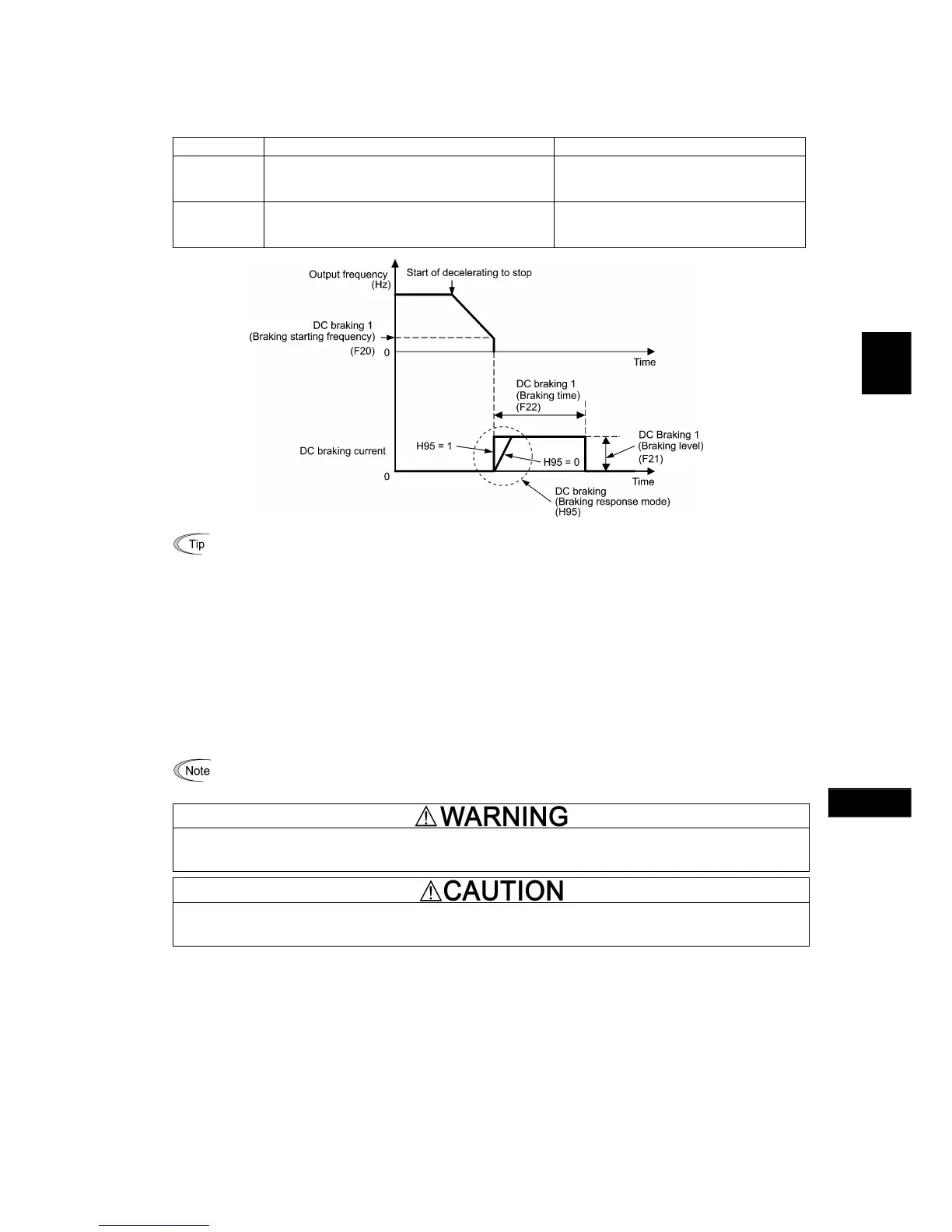
Braking response mode (H95)
H95 specifies the DC braking response mode. When vector control without/with speed sensor is selected, the response
is constant.
Data for H95 Characteristics Note
0
Slow response. Slows the rising edge of the current,
thereby preventing reverse rotation at the start of DC
braking.
Insufficient braking torque may result at the
start of DC braking.
1
Quick response. Quickens the rising edge of the
current, thereby accelerating the build-up of the
braking torque.
Reverse rotation may result depending on the
moment of inertia of the mechanical load and
the coupling mechanism.
It is also possible to use an external digital input signal as an "Enable DC braking" terminal command
DCBRK. As long as the DCBRK command is ON, the inverter performs DC braking, regardless of the braking
time specified by F22.
( Refer to E01 through E07, data =13.)
Turning the DCBRK command ON even when the inverter is in a stopped state activates the DC braking. This
feature allows the motor to be excited before starting, resulting in smoother acceleration (quicker build-up o
acceleration torque) (under V/f control).
When vector control without/with speed sensor is selected, use the pre-exciting feature for establishing the
magnetic flux. ( For details, refer to H84.)
In general, DC braking is used to prevent the motor from running by inertia during the stopping process. Under
vector control with speed sensor, however, zero speed control will be more effective for applications where
load is applied to the motor even in a stopped state.
If the zero speed control continues for a long time, the motor may slightly rotate due to a control error. To fix
the motor shaft, use the servo-lock function. ( For details, refer to J97.)
In general, specify data of function code F20 at a value close to the rated slip frequency of motor. If you set i
at an extremely high value, control may become unstable and an overvoltage alarm may result in some cases.
Even if the motor is stopped by DC braking, voltage is output to inverter output terminals U, V, and W.
An electric shock may occur.
The DC brake function of the inverter does not provide any holding mechanism.
Injuries could occur.
CTi Automation - Phone: 800.894.0412 - Fax: 208.368.0415 - Web: www.ctiautomation.net - Email: info@ctiautomation.net

 Loading...


