3-1
Chap. 3 OPERATION USING THE KEYPAD
Chapter 3 OPERATION USING THE KEYPAD (in the case of remote keypad)
3.1 LED Monitor, Keys and LED Indicators on the Keypad
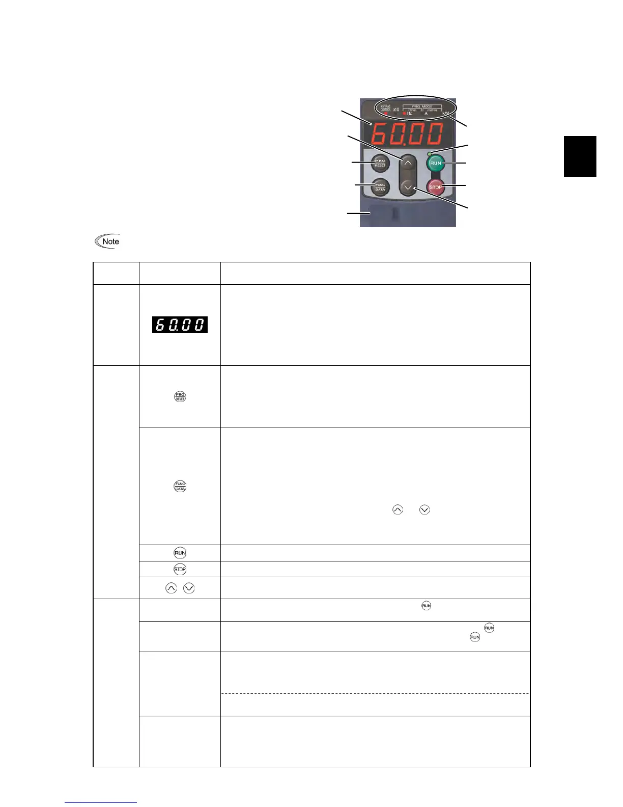
As shown at the right, the keypad consists of a
four-digit LED monitor, six keys, and five LED
indicators.
The keypad allows you to run and stop the motor,
monitor the running status, specify the function code
data, and monitor I/O signal states, maintenance
information, and alarm information.
When using a multi-function keypad instead of a remote keypad, read the Multi-function Keypad Instruction Manual.
Table 3.1 Overview of Keypad Functions
Item
LED Monitor, Keys,
and LED Indicators
Functions
LED
Monitor
Four-digit, 7-segment LED monitor which displays the followings according to the
operation modes.
In Running mode: Running status information (e.g., output frequency, current,
and voltage)
When a light alarm occurs,
l-al
is displayed.
In Programming mode: Menus, function codes and their data
In Alarm mode: Alarm code, which identifies the alarm factor when the
protective function is activated.
Program/Reset key which switches the operation modes of the inverter.
In Running mode: Pressing this key switches the inverter to Programming
mode.
In Programming mode: Pressing this key switches the inverter to Running mode.
In Alarm mode: Pressing this key after removing the alarm factor will switch
the inverter to Running mode.
Function/Data key which switches the operations you want to do in each mode as
follows:
In Running mode: Pressing this key switches the information to be displayed
concerning the status of the inverter (output frequency (Hz),
output current (A), output voltage (V), etc.).
When a light alarm is displayed, holding down this key resets
the light alarm and switches back to Running mode.
In Programming mode: Pressing this key displays the function code or establishes
the data entered with
and keys.
In Alarm mode: Pressing this key displays the details of the problem
indicated by the alarm code that has come up on the LED
monitor.
RUN key. Press this key to run the motor.
STOP key. Press this key to stop the motor.
Operation
Keys
/
UP and DOWN keys. Press these keys to select the setting items and change the function
code data displayed on the LED monitor.
RUN LED
Lights when running with a run command entered by the
key, by terminal command
FWD or REV, or through the communications link.
KEYPAD
CONTROL LED
Lights when the inverter is ready to run with a run command entered by the
key (F02
= 0, 2, or 3). In Programming and Alarm modes, however, pressing the
key cannot
run the inverter even if this indicator lights.
These three LED indicators identify the unit of numeral displayed on the LED monitor in
Running mode by combination of lit and unlit states of them.
Unit: Hz, A, kW, r/min and m/min
Refer to Chapter 3, Section 3.3.1 "Monitoring the running status" for details.
Unit LEDs
(3 LEDs)
While the inverter is in Programming mode, the LEDs of Hz and kW light.
Hz A kW
LED
Indicators
x10 LED
Lights when the data to display exceeds 9999. When this LED lights, the "displayed
value x 10" is the actual value.
Example:
If the LED monitor displays
1234
and the x10 LED lights, it means that the actual
value is "1,234 × 10 = 12,340."
LED indicators
DOWN key
STOP key
UP key
Function/
Data key
RUN key
7-segment
LED monitor
Program/
Reset key
USB port
RUN LED