5-29
5.2 Details of Function Codes
This section provides the details of the function codes. The descriptions are, in principle, arranged in the order of function
code groups and in numerical order. However, highly relevant function codes are collectively described where one of them
first appears.
5.2.1 Fundamental Functions
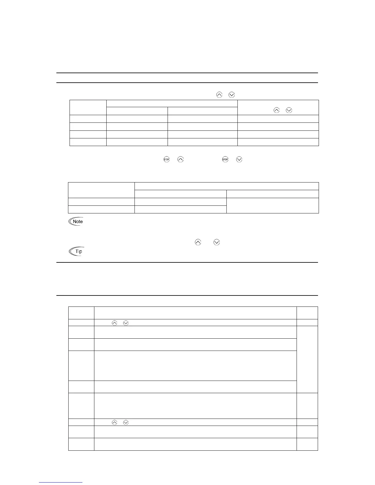
F00 Data Protection
F00 specifies whether to protect function code data (except F00) and digital reference data (such as frequency command
and PID command) from accidentally getting changed by pressing the
/ keys on the keypad.
Changing function code data
Data for F00
From the keypad Via communications link
Changing digital reference data
with the
/ keys
0 Allowed Allowed Allowed
1 Not allowed
*
Allowed Allowed
2 Allowed Allowed Not allowed
3 Not allowed
*
Allowed Not allowed
*
Only F00 data can be modified with the keypad, while all other function codes cannot.
To change F00 data, simultaneous keying of " + " (from 0 to 1) or " + " (from 1 to 0) keys is required.
For similar purposes, WE-KP, a signal enabling editing of function code data from the keypad is provided as a terminal
command for digital input terminals. (Refer to the descriptions of E01 through E07, data = 19)
The relationship between the terminal command WE-KP and F00 data are as shown below.
Changing function code data
WE-KP
From the keypad Via communications link
OFF Not allowed
ON Follow the F00 setting
Allowed
• If you mistakenly assign the terminal command WE-KP, you no longer edit or modify function code data. I
command.
• WE-KP is only a signal that allows you to change function code data, so it does not protect the frequency
settings or PID speed command specified by the
and keys.
Even when F00 = 1 or 3, function code data can be changed via the communications link.
F01 Frequency Command 1
F18 (Bias, Frequency command 1) C30 (Frequency Command 2)
C31 to C35 (Analog Input Adjustment for [12]) C36 to C39 (Analog Input Adjustment for [C1])
C41 to C45 (Analog Input Adjustment for [V2]) C50 (Bias (Frequency command 1), Bias base point)
H61 (UP/DOWN Control, Initial frequency setting) d59, d61 to d63 (Command (Pulse Rate Input))
F01 or C30 sets the command source that specifies reference frequency 1 or reference frequency 2, respectively.
Data for
F01, C30
Function Refer to
0 Enable / keys on the keypad. [ 1 ]
1
Enable the voltage input to terminal [12] (0 to ±10 VDC, maximum frequency obtained at ±10
VDC).
2
Enable the current input to terminal [C1] (+4 to +20 mA DC, maximum frequency obtained at +20
mA DC). (SW5 on the control PCB should be turned to the C1 side (factory default).)
3
Enable the sum of voltage (0 to ±10 VDC) and current inputs (+4 to +20 mA DC) given to terminals
[12] and [C1], respectively. See the two items listed above for the setting range and the value
required for maximum frequencies. (SW5 on the control PCB should be turned to the C1 side
(factory default).)
Note: If the sum exceeds the maximum frequency (F03), the maximum frequency will apply.
5
Enable the voltage input to terminal [V2] (0 to ±10 VDC, maximum frequency obtained at ±10
VDC). (SW5 on the control circuit board should be turned to the V2 position (factory default).)
[ 2 ]
7
Enable UP and DOWN commands assigned to the digital input terminals.
The UP command (any of E01 to E07 = 17) and DOWN command (any of E01 to E07 = 18) should
be assigned to any of digital input terminals [X1] to [X7].
For details, refer to the descriptions of E01 through E07.
[ 3 ]
8 Enable / keys on the keypad (balanceless-bumpless switching available). [ 1 ]
11
Enable a digital input interface card (option).
(For details, refer to the Digital Input Interface Card Instruction Manual.)
-
12
Enable the "Pulse train input" PIN command assigned to digital input terminal [X7] (E07 = 48), or a
PG interface card (option).
[ 4 ]

 Loading...


