the braking resistor and settings of related function codes.
The standard models of braking resistor can output temperature detection signal for overheat. Assign an
"Enable external alarm trip" terminal command THR to any of digital input terminals [X1] to [X7], [FWD]
and [REV] and connect that terminal and its common terminal to braking resistor's terminals 2 and 1.
Calculating the discharging capability and allowable average loss of the braking resistor and configuring the
function code data
When using any non-Fuji braking resistor, inquire of the resistor manufacturer about the resistor rating and then
configure the related function codes.
The calculation procedures for the discharging capability and allowable average loss of the braking resistor differ
depending on the application of the braking load as shown below.
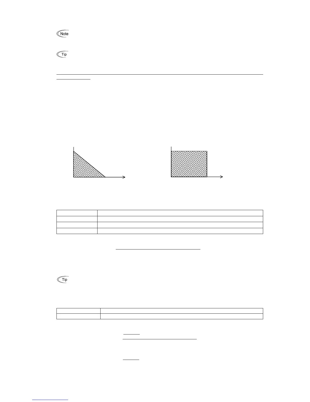
- Applying braking load during deceleration
In usual deceleration, the braking load decreases as the speed slows down. In the deceleration with constant torque, the
braking load decreases in proportion to the speed. Use Expressions (1) and (3) given below.
- Applying braking load during running at a constant speed
Different from during deceleration, in applications where the braking load is externally applied during running at a
constant speed, the braking load is constant. Use Expressions (2) and (4) given below.
Applying braking load during deceleration Applying braking load during running at a constant speed
Discharging capability (F50)
The discharging capability refers to kWs allowable for a single braking cycle, which is obtained based on the braking
time and the motor rated capacity.
Data for F50 Function
0 To be applied to the braking resistor built-in type
1 to 9000 1 to 9000 (kWs)
OFF Disable the electronic thermal overload protection
During deceleration:
Discharging capability (kWs) =
2
Braking time (s) × Motor rated capacity (kW)
Expression (1)
During running at a constant speed:
Discharging capability (kWs) = Braking time (s) × Motor rated capacity (kW) Expression (2)
When the F50 data is set to "0" (To be applied to the braking resistor built-in type), no specification of the
discharging capability is required.
Allowable average loss (F51)
The allowable average loss refers to a tolerance for motor continuous operation, which is obtained based on the %ED
(%) and motor rated capacity (kW).
Data for F51 Function
0.001 to 99.99 0.001 to 99.99 (kW)
During deceleration:
Allowable average loss (kWs) =
2
× Motor rated capacity (kW)
100
%ED(%)
Expression (3)
During constant speed operation:
Allowable average loss (kWs) =
× Motor rated capacity (kW)
100
%ED(%)
Expression (4)
Resistance (F52)
F52 specifies the resistance of the braking resistor.
Time
Braking load (kW)
Time
Braking load (kW)